Unravelling the Secrets of a 22-in. Pipeline Using EM Technology
“A 22-in. diameter pipe? – that must be a mistake!” – was my initial reaction when reading the email heading. I had fully convinced myself that this had to be a 24-in. pipe until I started reading through the project questionnaire. In the questionnaire the pipeline owner, clearly outlined that the effluent pipeline was fabricated using 22-in. in diameter steel pipe with a nominal wall thickness of 7.14 mm.
It subsequently became clear that the pipeline owner was a very capable operator who cleans the pipeline regularly using pigs, and who was looking to assess the condition of this critical piece of buried infrastructure in British Columbia.
The 2 km long pipeline transports effluent water from a mill, and if it were to fail, the production of the plant would be halted until repairs were completed (where does one get 22-in. pipe in a hurry?). As a result, the almost 40-year-old pipeline scored high in the plant’s reliability risk rankings, and the mill started looking for an inspection solution.
At this point, a perceptive reader is likely thinking: If 22-in. pipe is uncommon, a 22-in. inspection tool surely must be even less common. This would indeed be true if it weren’t for the fact that remote field testing (RFT) inspection tools are primarily designed for internally lined pipe. These types of tools employ electromagnetic (EM) technology to quantify the pipe wall thickness through internal liners and scale.
The internal liners can be over 1-in. thick for certain liner materials, and as a result an RFT tool for 24-in. lined pipe happens to be perfectly suited for a 22-in. unlined pipe. Upon realizing this, the pipeline owner approached PICA Corp. in Edmonton, Alberta, regarding deployment of its RFT tools in the effluent line, and representatives from PICA performed a site visit in 2017.
RELATED: EM Technology — A Practical Discussion
Inspection Approach and Preparations
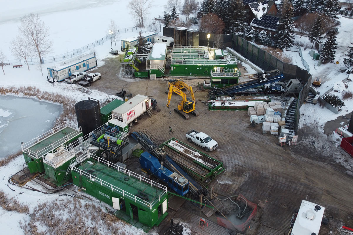
Over the years, the mill had installed a wye near the river, which allowed them to send cleaning pigs from the river back towards the plant using pumped river water. That same wye could be used to send an internal RFT inline inspection tool through the pipe, and plans were made to attach an extended launch barrel to the wye lateral in order to launch the inspection tool (see photo on at top).
Prior to the RFT inspection, the pipeline operator wanted to ensure that the inspection equipment was in fact sensitive to wall loss, and in consultation with PICA, the mill introduced three defects a short distance away from the access wye. The defects were made by grinding 30 per cent, 50 per cent and 70 per cent deep flaws into the crown of the pipe.
The image above shows the location of the defects, the defects themselves and the corresponding RFT inspection data. Because the defects had well defined depth, they double functioned as calibration defects for the RFT inspection tool.
RELATED: Urban Assessment City of Montreal Looks at Its Aging Infrastructure
Inspection and Results
On a sunny morning in May 2018, PICA’s RFT inspection tool was successfully launched into the effluent line and sent on its way using pumped river water. Above ground crews closely tracked the tool as it made its way from the launch wye towards the mill.
After a 10.5 hour journey the inspection tool arrived safely in the plant’s splitter box, having gathered valuable information on the pipe wall thickness of the effluent line along its way. The tool was extracted using a picker truck, and the inspection data was immediately downloaded and reviewed.
The inspection resulted in the identification of several localized wall loss indications. Of these indications the vast majority was located at or near the girth weld joints. Only 37 “mid-span” defects were found in the bodies of the pipe. The remaining wall loss indications were all located within 15 cm of a girth weld connection between two pipe sticks, pointing at possible failure of the external weld sleeves.
An example is shown in the data screen capture on pg. 25, which displays RFT data from the weld area between pipe sticks 210 (left side of weld) and 220 (right side). The pipe looks a little darker on the right of the weld, due to (slight) changes in the material properties of the steel of pipe stick 220 (vs that of stick 210). This particular weld exhibited a number of pronounced wall loss indications, visible as bright white yellow patches in the data screen capture below.

PICA RFT data from a weld joint in the 22-in. effluent line. The bright coloured patches are deeper corrosion indications on either side of a girth weld. Because of the size of the indications, this particular weld was selected as a dig location by the plant.
Based on the data in the screen capture, the joint between pipes 210 and 220 was flagged as a possible verification site, and plant personnel performed a dig. Upon exposure of the joint, it had become apparent that moisture had become trapped under the weld sleeve and had initiated external corrosion.
RELATED: PICA Called Upon to Inspect, Assess Steel Force Main for Otay Water District
The RFT signal indication at the 2 o’clock position (referred to as Indication #3 in the data screen capture on pg. 25) proved to be a small perforation (visible after sand blasting). As a result of the RFT inspection, the plant’s integrity and reliability engineers have gained considerable insight into the condition of their pipeline.

Thirty per cent, 50 per cent and 70 per cent deep defects introduced into the crown of the pipe prior to inspection with corresponding RFT data below. The 35-mm by 35-mm defects were repaired after the inspection run.
It has become clear that the effluent line primarily suffers from problems at the girth welds, and that the bodies of the pipes are in good shape. The problems at the welds are likely due to sleeve failures as a result of poor installation during the original construction of the pipeline. The weld sleeve failures result in moisture becoming trapped between the pipe and the sleeve inducing external corrosion in the weld areas.
Although none of the areas identified by the inspection pose an immediate integrity threat, the worst affected weld areas will be repaired, re-sleeved and anode protected during upcoming shutdowns to ensure uninterrupted production at the mill.