EM Technology — A Practical Discussion
The growing use of Electro-Magnetic or “EM” technology in wireless steering systems has expanded in several market segments over the past few years. Applications for river crossing, utility installation, monitoring, and traditional oil and gas are rising in key markets worldwide. The promise of a reliable and wireless communication system for downhole steering operations has proven itself convenient and profitable. How do you know if you’re ready to implement an EM system, and how do you configure your new setup? Continuing advances in EM technology over recent years have made this process simple and easy to understand, providing the HDD industry with exciting new possibilities in survey system configurations
In February 2018, we wrote in Trenchless Technology about how EM technology has been used for years in oilfield operations. Our article included the basic components of the system and how each functioned as a reliable piece of a drilling operation.
The elements of an EM system; including the antenna, mechanics of signal transmission, data rates and frequency were included. What we didn’t have space to highlight were some of the successful applications of EM systems in Coal Bed Methane (CBG) and surface to in-seam (SIS) drilling plans, or the application of production pressure testing and monitoring.
EM as a Communication Platform: The Brains of the System
The wireless transmission of information in an EM system permits lower data rates when compared to wired systems, but a well configured and smart operation doesn’t result in any reduction of drilling information. By varying the frequency of surveys, deploying the right sensor package, and even in some cases rotating the tool face in hole — the CPU can consolidate the results of each survey and then transmit the most actionable information to the operator. Your EM system manufacturer will have a procedure to program your tool for variety of run types, in many cases with software support to optimize and support your team.

Sensor Package Configurations
The sensor market has continued to grow the variety of options for EM operations. The evolution of smart sensors, onboard calibration, and a variety of resolution settings have increased the options for EM applications. Many EM manufacturers offer sensors with HiResolution directional data, pressure sensors, gamma, resistivity or other custom capabilities for the drilling work of the client. The EM system acts as a communication driver for the sensors that are selected for the equipment.
RELATED: Product Profile: Direct Horizontal Develops Wireless HDD Tool
Communication Bandwidth Management
A critical element to consider in accepting EM communication is the data transmission rate. After all, operators are trading the cost, hassle, and risk of wires to wireless transmission. Across the EM tool marketplace, the typical data rate is 12 bits/second, which makes every transmission valuable. The onboard computer system builds a package of the most useful information for the drill site. The data is sent to the operator who reads it on a display. The data can also be sent to other programs for additional processing.
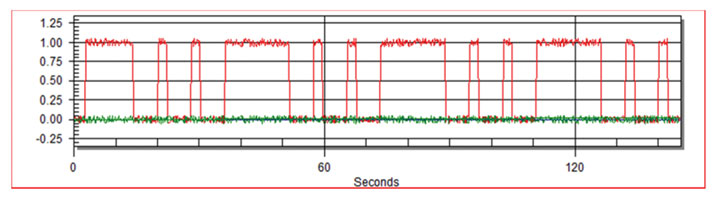
Message packages send a burst of information. In this view the RED line represents power being delivered onto the drill string to carry information. The first block begins with synchronization data. The short blocks represent frequently needed data like toolface or pressure. The longer blocks represent the full sensor vector information for station updates. This image will vary based on the selections made by the operator during programming and will follow the dynamics of the drillstring motion to send selected data during sliding and drilling rotation.
EM Power AMP and Battery Management
The longevity and management of an EM system’s power source is one of the most important pieces of designing your EM system and drilling plan. The EM system can be put to sleep and woken up by the operator, in addition to controlling variable transmissions like survey type and interval while running. EM systems can be run with Alkaline or Lithium batteries, and battery longevity can be forecasted by the type and time of operations. When planning an EM drill, be mindful of power flow, discharge rate, and avoid abusing the battery with a high sustained draw, which can exhaust batteries prematurely.
EM Surface Configuration
The typical EM surface system has unique requirements. It is typical for EM systems to require “attenna wires” that run from locations at the rig site to the surface equipment. These wires are usually simple 10 awg. One wire will go directly to the rig. A second wire will go to a point in the field and attach to a ground stake. These two wires can be thought of as probe leads used on a simple digital volt meter. They will often run through a barrier box that is designed to prevent high voltage spikes from damaging the receiver equipment.
RELATED: Robotic Pipeline Technology Extends the Life of Gas Pipelines

A Retrospective on the Advantages of EM
The main advantage of an EM system is the reduction in time, cost, and risk with wired transmission. However, several operators have used EM technology to consider new opportunities where it is not practical to run a wired system or a walkover system. In some cases, it may be possible or profitable to do a job but the wireless system reduces need for having a person on the rig making up the wire. Reducing the frequency and need of this dangerous job can assist with compliance and reduce the chances of a costly injury or accident.
Reducing wire management time improves overall drill efficiency, but also helps firms comply with new requirements to pull drill strings out of hole for mandated inspections or later reaming. Not being reliant on wires also prevents lost time due to wire failure and splicing. Also, EM operator score points with their inventory and waste management teams by reducing the waste wires leftover from drill operations.