Surveying the Newton Force Main HDD Crossing
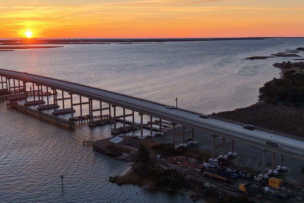
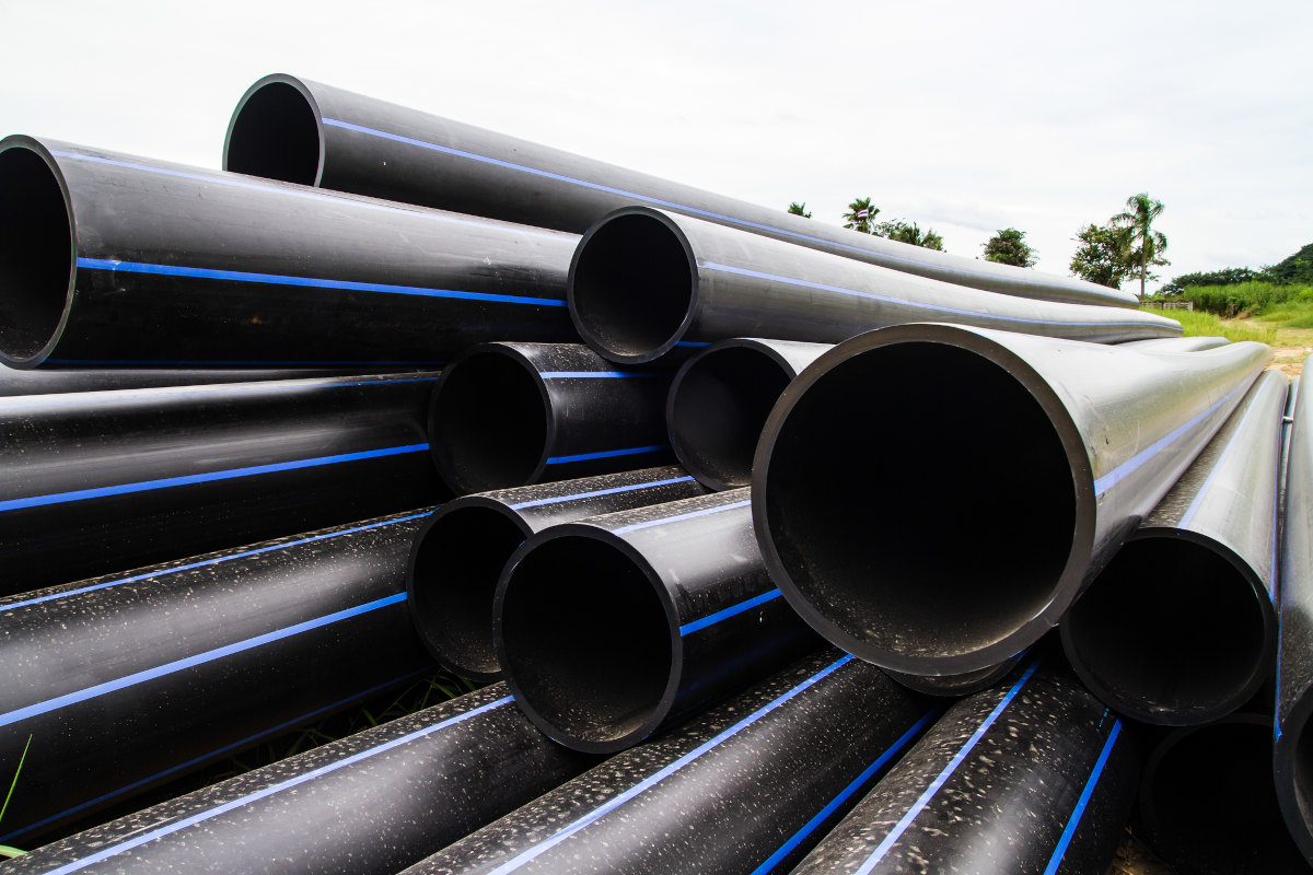
Brownline Canada was contracted in early 2023 to provide underground horizontal directional drilling (HDD) guidance services utilizing the proprietary Drillguide Gyro Steering Tool for construction of the Newton Force Main replacement under the Red River on the north side of the City of Winnipeg. The new 500-mm OD HDPE force main replaces an existing 350-mm HDPE pipe constructed in 1977.
The Newton Force Main carries sewage flows from the Linden and Hawthorn Districts east to a secondary sewer line west of the Red River. A 2018 inspection of the HDPE force main determined that the pipe had leaks and excessive deformations which required the construction of a replacement pipe.
Feasibility studies took place to decide whether the HDD installation method would be suitable in the bedrock formation under the river. Geotechnical investigations revealed that the ground formation consisted of alluvium soil over lacustrine clay, glacial silt till, and limestone bedrock with cobbles and boulders assumed to be present. Following careful evaluation of environmental impacts, constructability, future infrastructure, and geotechnical considerations, a drill path design for the crossing was selected to be executed by HDD using the intersect method (Figure 1). This method utilizes two drilling rigs on either end of the crossing to drill pilot bores towards each other to a planned intersect zone.

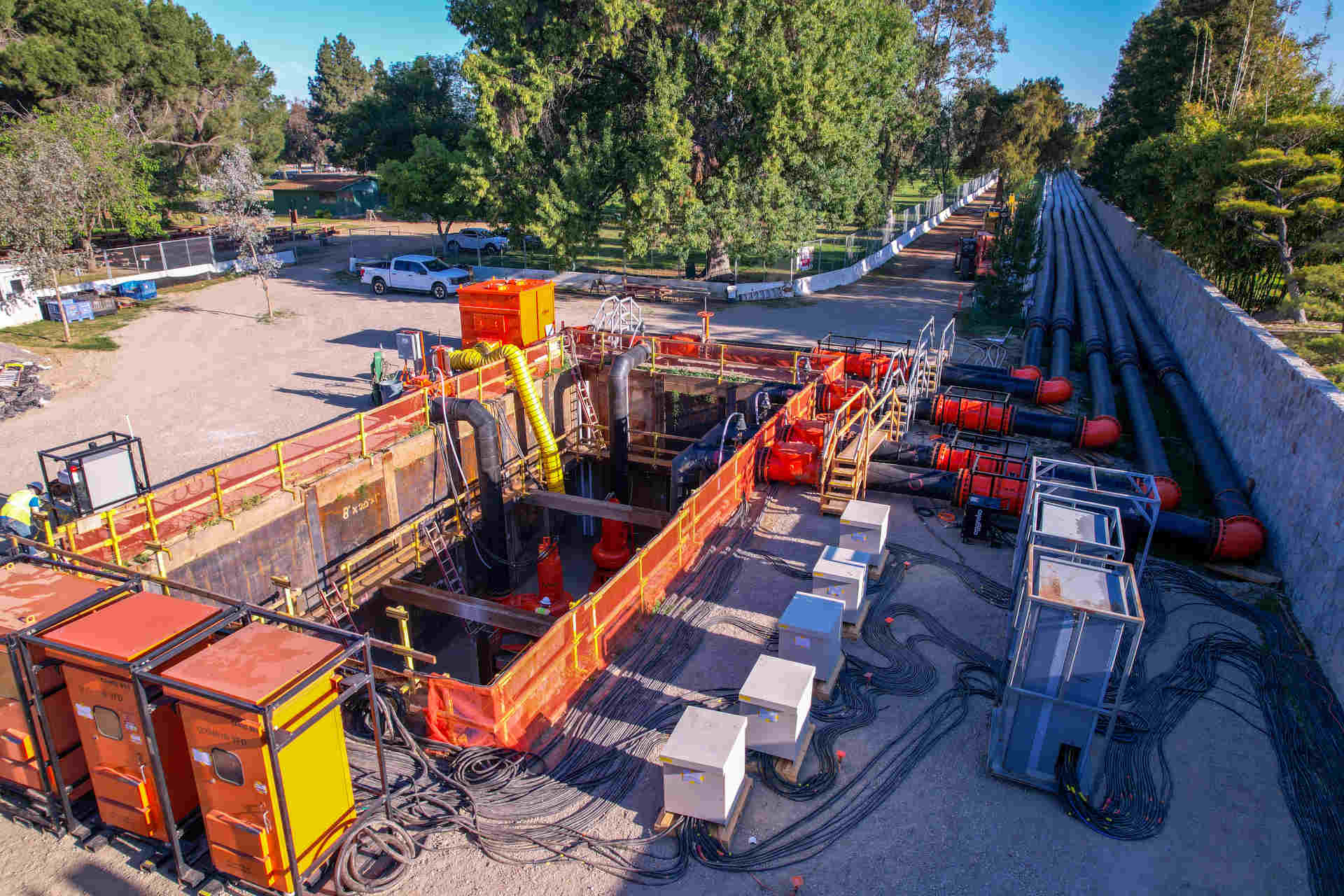
The drill path stretches 466 m across the Red River between Fraser’s Grove Park in the south (entry side) and Kildonan Park in the north (exit side). The design parameters consisted of 18-degree entry and exit angles, 350-m vertical curves and a 350-m horizontal curve at 12 degrees. Radial specifications allowed a maximum radial deviation of 2 m of the design path with a minimum allowable radius of 225 m. A 45-m long 36-in. diameter steel conductor casing was installed at exit side. Surface casing is used to support the integrity of the bore hole at shallow depths of cover and to prevent any possible inadvertent mud releases from occurring at the start of the bore. The same casing set up was installed at entry side at a length of 71 m. The surface casings on both sides were seated approximately 1.5 m into the bedrock formation.
The gyro steering tool was used to measure the casing. Gyro technology allows for an accurate logging of the steel casing as the tool is not disrupted by passive interference induced by the casing as a magnetic tool would be. The gyro tool recorded inclination and azimuth for every 3 m as the drill pipe was advanced. This frequency of recorded shots allowed for a more accurate calculation of the drill head position in real-time and subsequently a more precise as-built.
Brownline analyzed the designed drill path and was asked by the contractor, Accurate HD Ltd., to provide two execution proposals of the most suitable intersection zone on the exit side. Tangent sections are the ideal locations along a drill path to plan an intersect zone as the risk for exceeding the specified radius tolerance is minimized. The drill path offered short tangent sections which at exit side was further constricted by the measured location of the exit side surface casing post installation. Two zones were identified: the first one at the exit tangent which provided a 36 m intersection zone, and the second, a 12 m tangent zone at the bottom tangent between the horizontal curve and the start of the exit vertical curve.
While the first proposal offered more room, the measured location of the surface casing proved to be a major constraint should the intersection attempt miss the 36-m window. The second proposal was considered more feasible after considerations of the tool’s accuracy were made. The Drillguide gyro steering tool has a stated accuracy of ±0.04 degrees on the azimuth plane which, at approximately 190 m from the exit side, the maximum deviation was projected to be ±0.13 m. The maximum deviation from the entry side was calculated to be ±0.19 m. These deviation values suggested that the likelihood of missing the intersect because of the tool’s margin of error was low. Part of the execution plan consisted of deploying Drillguide Radar systems as a contingency should the first intersection attempt not be successful. These systems are activated to communicate with one another and determine the relative horizontal and vertical separation between two bores.
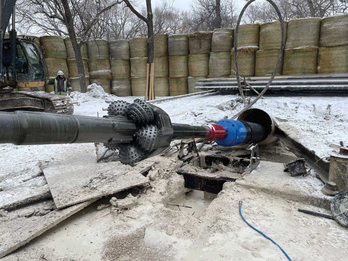
Pilot hole operations commenced first at the exit side. Accurate HD utilized a 100,000 lbs drill rig at exit side with an average of 49 m drilled every 24 hours. The bottom hole assembly (BHA) consisted of a 9-7/8-in. tricone drill bit with a 6-3/4-in. diameter mud motor to drill the exit side. The gyro tool and the radar system were installed in sequence behind the motor. A total of 200 m was drilled from exit side which included 110 m of vertical build. The calculated position of the gyro was 0.94 m right of the planned trajectory and 1.31 m below largely dictated by the measured location of the surface casing. At this position, the pre-bore plan was updated for the entry side to intersect at that point.
A similar BHA was set up at entry side where the contractor used a 330,000 lb drill rig. The rate of penetration was higher at entry side due to the increased pump output made possible with a larger rig and support equipment. An average of 129 m was drilled every 24 hours. The remaining 266 m drilled included a vertical curve and the 12-degree horizontal curve. The intersection was successfully completed at the precise calculated position of the exit side bore following fluid communication between both sides. The transition point was smoothed and augmented by making several passes with the drill head through that zone at different orientations. The minimum combined radius at the intersection zone was 229 m.
Entry side then advanced in the drilled bore to exit side with the gyro tool continuing to capture surveys every 3 m. The pilot hole as-built was approved and the contractor proceeded to ream and successfully install the pipe. The maximum recorded pull force during pullback was 52,000 lbs at the transition point which was well below the engineer’s anticipated pull force of 130,000 lbs.
Chris Frisch is operations manager at Borwnline Canada. Mohammed Al-Wazir is project manager at Brownline Canada.