Drill Master: Electronic Equipment in HDD
In recent years the advancement of technology in the electronics field has made electronic equipment the key element in the viability of directional drilling.
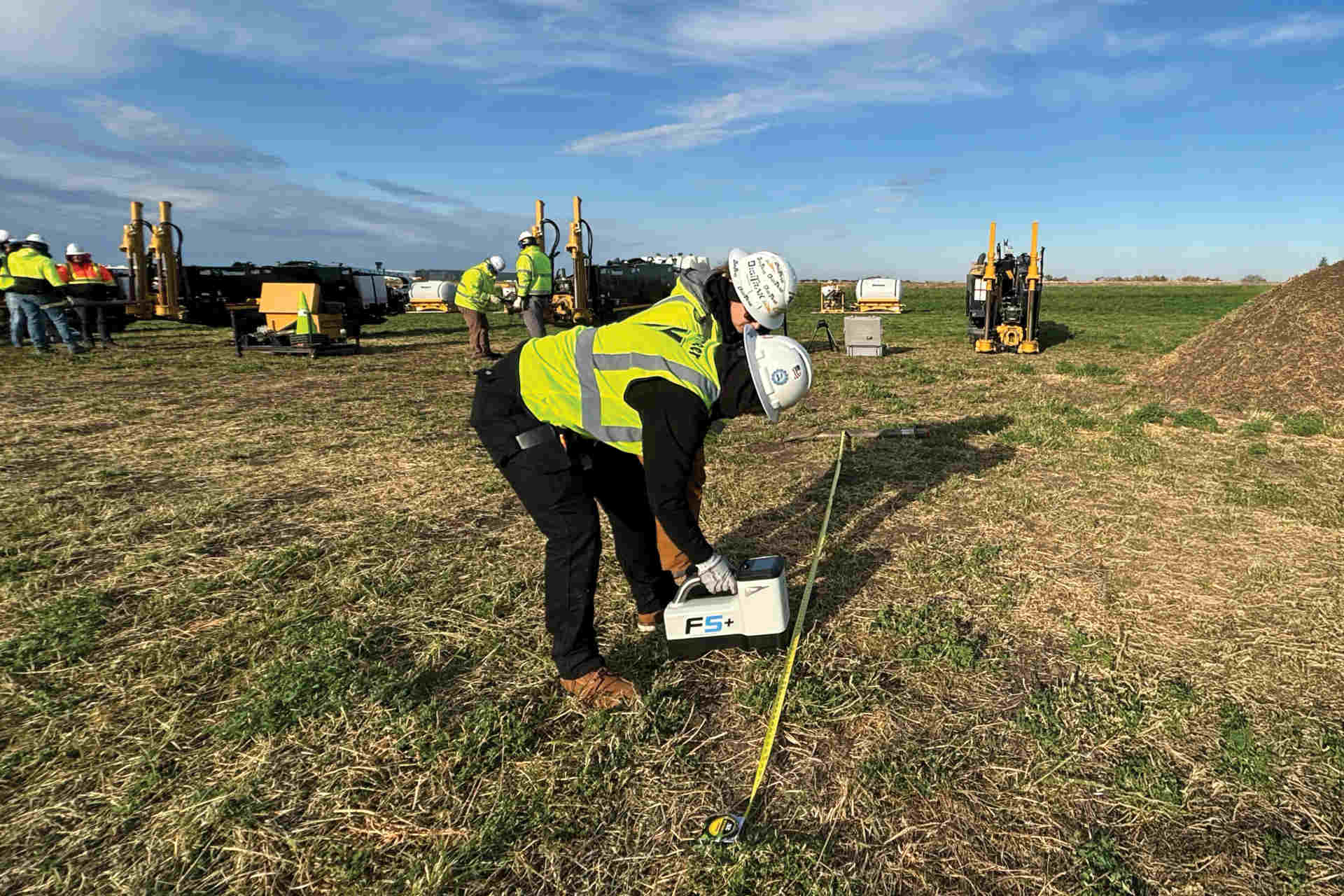
Electronic tracking systems are “the eyes” of the directional drilling operation, functioning much like an instrument landing system in the field of avionics. A typical electronic tracking system consists of a transmitter, receiver and remote display unit located at the drilling rig. The transmitter has on-board sensors that sense the orientation of the drill bit, pitch, battery status and temperature. It transmits this information to the receiver, allowing necessary course corrections to be made.
There are several ways to improve the usefulness of tracking electronics:
Planning the Bore
In addition to a visual survey of the bore site for interfering overhead power lines and transformers, one electronic manufacturer provides a method for pre-surveying the bore path. Potential external noise (interference) between the transmitter and the receiver can be evaluated simply by walking the bore path with the receiver and taking depth readings with the transmitter turned off. Generally the deeper the “passive” (no transmitter source) depth reading the less noise interference can be expected.
A rule of thumb for Subsite electronics, for example, is that passive depth readings will be effective to about 66 percent of the depth reading. Areas of strong interference can be identified. In these cases, if locates and depth readings are disrupted, pitch, roll and other guidance information will still be available.
Another useful application is to lay the transmitter on the ground surface to determine the pitch necessary to match sloping terrain. This information helps determine the setup angle of the machine and setup space needed to get to minimum cover depths. Used properly it can eliminate guesswork throughout the bore.
Preparing Electronic Equipment
Prior to the bore, electronic equipment should be inspected and in some cases calibrated. Most start-up problems revolve around batteries or battery contacts. Make sure the batteries are correctly installed and all contacts are clean. New batteries should be used in the transmitter for each bore.
Because of the harsh drilling environment, transmitter batteries survive better if they are spot welded and shrink wrapped together. When not available, dielectric grease should be applied between the batteries and then the two batteries should be taped together.
It is very important to keep both the transmitter and the receiver at least 30 to 50 ft (9 to 15 m) from any metal, power lines or transformers during calibration to avoid difficulties with electronic performance while drilling. This is necessary to allow the receivers to estimate the depth at deeper ranges.
Boring Tips
The following information provides additional drilling tips with electronics. In normal locating of the transmitter, with walkover receiver antennas positioned in line with the transmitter, the areas just in front and behind the transmitter will provide a false strong signal, known as a “ghost.” Depending on the transmitter orientations, there are various methods of coping with and using these ghost signals.
Front to back locate: With Subsite’s “GhostBuster” function, for example, locate the transmitter normally (in line with the drill string). The strongest signal (peak) is the suspected transmitter location. Press and hold the depth button for about two seconds. If the drill head is properly located, all roll segments on the receiver LCD will light. If you have located a ghost signal, an arrow above the ghost signal will light. This feature only works when the receiver is within 8 ft (2.4 m) of the transmitter. Continue locating and ghost check until the proper transmitter location is found.
Deep left to right locate: As a transmitter goes deeper, the side to side locate gets broader and more difficult to narrow down. This is where the ghost signal can help achieve a more exact location. Locate the transmitter normally. Starting from the strongest signal, move the receiver forward along the projected bore path. The signal will reduce to almost null and then begin to increase in strength (the beginning of the front ghost). Move back until the null point is located and turn the receiver 90 degrees or perpendicular to the bore path. Move the receiver back and forth across the bore path and find the null point. Mark this spot. Now move to the rear ghost and repeat the process. This technique will give you three points to line up for a more precise left/right locate.
Misleading depth and location: Areas with a heavy concentration of conducting metals, such as rebar, metal buildings, pipes or chain link fences, can lead to distorted fields and erroneous readings. When you are in a heavy metal area, all depth readings and locates should be suspected as erroneous. Typically your guidance information (pitch, roll, left/right) is useful. Attempt to plan your bore so you will be boring level during those disruptive areas. Pitch roll and left/right can be monitored and corrected to help ensure the bore is consistent until you leave the area and your electronics return to normal operations.
The horizontal drilling industry has witnessed large strides forward in reliability, versatility and usefulness of electronics equipment. The next few years likely will bring even greater value to the industry by further advancement.


Comments are closed here.