Tech Forum: Microtunneling Guidance System Set-Up for Favorable Results

Landherr
On a microtunneling project, the shiny microtunnel boring machine (MTBM), its robust cutting tooling, and cavernous shaft are always a source of fascination. However, they often overshadow one of the most significant elements of the microtunneling operation, the guidance system.
The most successful microtunneling projects are those that adhere to systematic procedures during guidance system set-up for a desirable outcome – calibration, proper set-up, instrumentation isolation, controlled tunnel atmospherics and periodic survey checks.
RELATED: Tech Forum – Maintenance Practices for Guided Boring System Operation and Storage
Since the laser system is the most common variety of microtunneling guidance instrumentation, we refer to this type. Please note that extended length and curved alignments require specialized guidance systems which are not addressed here.
Pre-Launch Set-up and Calibration
The guidance system camera is the primary reference for the operator to check the location of the target in the rear of the MTBM and ascertain the alignment’s line and grade. Therefore, a thorough pre-launch calibration and good set-up are equally as crucial to the alignment’s success as the operator’s control.
The guidance system camera must be set-up and calibrated according to the manufacturer’s recommendations before the launch.
Next, inspect and clean the MTBM’s target display.
Conduct a pre-launch functionality check consisting of calibrating the inclinometers and roll sensors to ensure correct machine attitude feedback.
Activate the target screen programs from the control console. When the programs are visible, check to make sure that the MTBM and launch cameras are operational from the control console.
The theodolite will require a tilt offset and collimation check before operation. These checks should also be performed following a strong vibration, bump or suspected disturbance to verify that the instruments are still operating within acceptable tolerances. If advanced accuracy is required before a long drive, a factory administered calibration from the guidance system manufacturer should be considered.
Lastly, if you’re in a position where there is outstanding information related to the guidance system set-up such as the designed tunnel plan or surveyor scale factor, wait to launch the MTBM until they’re resolved.
RELATED: What Makes a Good Concrete Jacking Pipe?
Guidance System Camera Installation and Protection
Most microtunneling guidance systems utilize an active laser as a fixed reference point, which is directed along the tunnel’s centerline at line and grade and projected onto the active target in the MTBM. The active target contains photosensitive cells that read and convert the information to digital data, which is electrically transmitted to the control console for the operator to interpret. Any movement can deflect and distort the camera’s reference point, so it is essential to take measures for its protection.
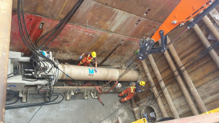
After the hydraulic jacking frame is positioned in the launch shaft, the laser mount is constructed behind the jacking frame in a manner that isolates the instrumentation from movement. Be sure that the mounting apparatus is not tied into structures that will experience jacking forces, including shaft walls or the reaction block. The mounting system apparatus should be not impacted by vibrations from mining or above ground operations. If the guidance system requires additional support equipment (i.e., reference prisms, cables, etc.), the mount location should accommodate accessibility to these additions.
The guidance system camera must be housed in a way so that it is shielded from mining operations and overhead debris. Most microtunneling hydraulic jacking frames feature a thrust block with a target space in the reaction wall so the laser can sight down the centerline of the pipe.
Controlling the Tunnel Atmosphere
The active target coordinates are transmitted to the operator in the control container to inform MTBM positioning. Because the software reads the location of the most intense light, tunnel atmospherics including humidity, heat, and temperature gradients, impact the laser’s clarity on the target.
Humidity in the tunnel creates water particulates that cause laser refraction and dispersion and deter an accurate target reading. Temperature gradients also affect laser refraction. Heat in the tunnel is created by tunneling equipment (booster pumps, motors, hydraulic hosing, on-board power pack) and produces temperature gradients which are compounded by the inherent nature of a warmer underground environment. Freezing temperatures can also contribute to laser distortion and diminished clarity.
The best way to control tunnel atmospherics is a tunnel ventilation system to circulate air movement and create a consistent tunnel atmosphere to present a more pointed laser beam. Ventilation will regulate temperature and humidity and reduce laser refraction and dispersion.
RELATED: Microtunneling Equipment Winterization Best Practices
System Check During Microtunneling Operations
Periodic checks during mining operations are recommended to ensure that the MTBM is plotting an accurate course.
Many guidance systems offer an automatic or manual real-time assessment of the MTBM’s position at any mining interval. Refer to the guidance system manufacturer for recommended survey intervals. We advise to record survey records both digitally and manually in the project’s shift logs.
Lastly, it is important to understand possible system errors and how to troubleshoot them. The ability to promptly identify and resolve an issue with the guidance system will greatly reduce potential down time.


