Robotic Technologies Used as a Condition Assessment Tool
In the 1960s, the City of Houston constructed a 60-in. raw water line together with two other 60-in. potable water lines. The three lines’ alignment crossed the Houston Ship Channel and conveyed water to and from the City’s East Water Purification Plant (EWPP). Of the three water lines, the two 60-in. potable lines were constructed, put in service, and have remained in service. The 60-in. raw water line has had a more storied history.
The 60-in. raw water line was initially constructed to convey water from an existing 42-in. water line to an existing 60-in. water line that conveyed water to the EWPP. This initial phase of construction included several interconnects, an aerial crossing, crossing the Houston Ship Channel, two valve houses and several sections of concrete encased pipe. The 60-in. raw water line was modified in the 1980s and two new segments were constructed to extend the raw water line. The extension connected the raw water line directly to a Coastal Water Authority (CWA) 72-inch water line and the EWPP.
After completion of the 1980s segment, the 60-in. raw water line remained in service nearly 10 years before CWA completed a 102/96-in. raw water line that provided additional raw water supply to the EWPP. After this line was completed, the City did not need the 60-in. raw water line capacity and a portion of the raw water line was isolated and put out of service. While leaving a short segment to feed one customer located on the line, just over 6,000 lf of the raw water line was isolated and remained out of service. In 2011, a major drought resulted in water demands that required the City to pump and treat nearly all available raw water influent. After this drought, the City chose to re-energize the 60-in. raw water line to meet future demands and engaged Lockwood, Andrews & Newnam Inc. (LAN), a planning, engineering and program management firm, to assess and restore the water line.

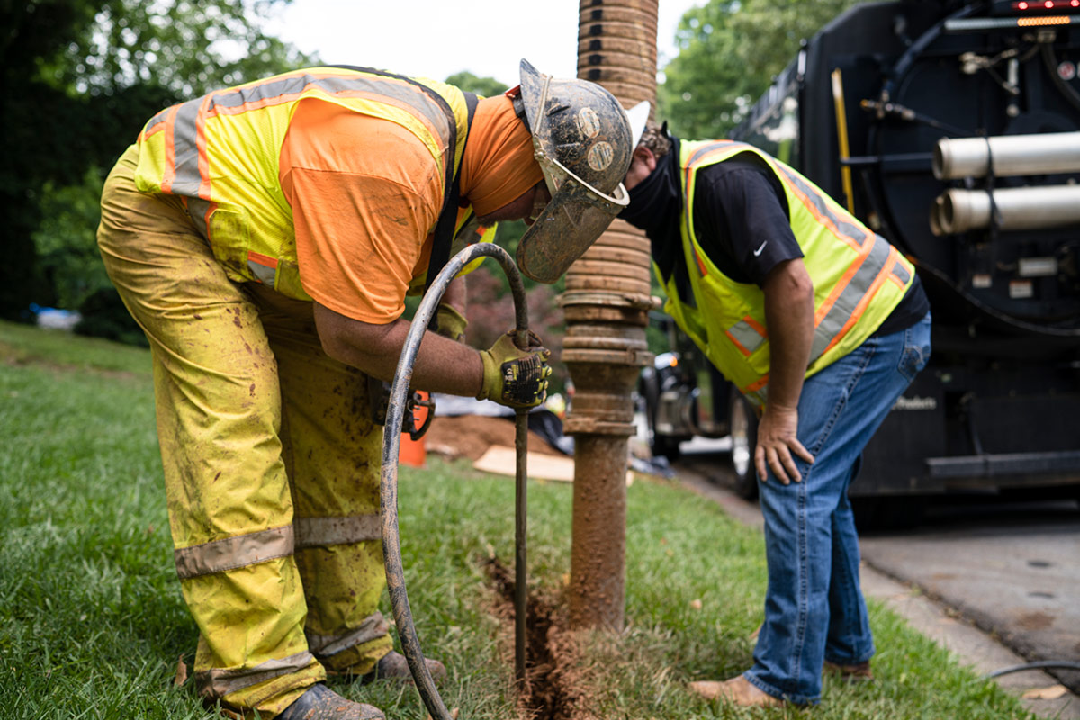
Ultrasonic Thickness Testing being done by the crew.
Design & Support Contract
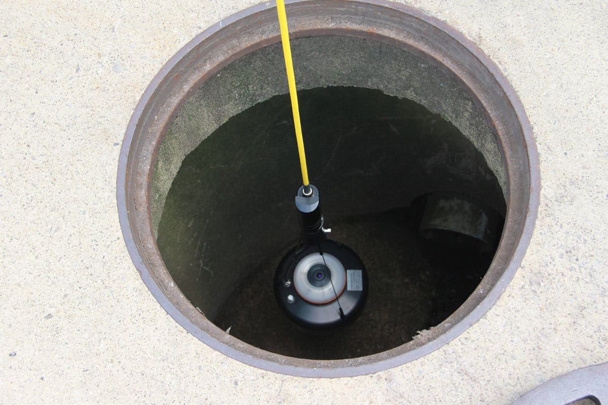
With the age and condition of the pipeline unknown, the project team needed to confirm the structural integrity of the pipeline and acquire installed pipe alignment information. Robotic inspection technologies, coupled with manned-entry condition assessment, were used to assess the current condition of the pipe. Specific technologies used included closed circuit television (CCTV), and 3D laser inspection. LAN prepared a condition assessment support contract, now complete, which included the robotic inspection, manned-entry inspection and pressure testing of the pipeline.
The intent of the support contract was to provide a pipeline prepared to convey water and a thorough assessment of the condition of the pipeline. This required incorporating several improvements to facilitate the condition assessment and provide contractor support for required repairs. As part of the support contract design, parameters for assessing the pipeline had to be determined and methods for inspection planned. The following components were selected for inspection:
• North Valve House
• South Valve House
• Butterfly Valves in each Valve House
• Cathodic Protection System
• Aerial Crossing at Vince Bayou south of the ship channel
• East Water Purification Plant Aerial Discharge Pipe
• Ship Channel Crossing
• All other Buried Pipe
A majority of the alignment was selected for manned-entry, 3D laser inspection and supplemental CCTV inspection. In the event the ship channel crossing could not be dewatered, a 3D sonar inspection was included.
Upon completion of the design, the City awarded the construction contract to Huff and Mitchell Inc. After notice to proceed, the contractor mobilized and began the following preliminary work to facilitate the condition assessment:
• Install new manways and air release valve improvements
• Install potential test stations
• Dewater water line
• Clean water line
Dewatering the water line required multiple-point continuous pumping throughout the condition assessment to maintain low water levels during inspection. After dewatering, the pipeline was cleaned and prepared for inspection. The contractor remained active to provide confined space entry assistance and means for making repairs so the raw water line could be reinstated after the assessment.
Condition Assessment Inspections
The condition assessment was broken into several segments and the entire water line excluding the ship channel crossing was inspected manually and robotically. An initial CCTV inspection of the ship channel confirmed that even the lowest sections of pipe had been dewatered. Following the initial inspection of the ship channel, a 3D laser inspection (Lidar) with supplemental CCTV footage was performed. The robot was remotely controlled through the pipeline stopping every 5 ft to perform a laser scan of the pipe. As the inspection progressed, the subcontractor’s crew would log any defects noted in the CCTV footage and enter the pipeline to manually assist movement when the robot encountered obstacles. While the 3D laser inspection data was being processed, the manned-entry inspection was performed.
For manned-entry inspection, the pipeline was assessed by a group of three to four engineers. The assessment included non-destructive observations and documented any noted defects ranging from deterioration in pipe lining, un-grouted joints, pipe deflection, displacement in bends, and visual signs of corrosion. For the above ground pipe sections and any exposed pipe wall segments displaying signs of local corrosion, ultrasonic thickness testing was performed. In a few locations, the contractor was asked to remove short segments of internal mortar lining where signs of corrosion were visible in the lining to test the thickness of the internal wall of the steel pipe. Initial Lidar results were received after a month but it took several months to continue processing data from the Lidar inspection. During this time, the contractor addressed several deficiencies located during manned entry. These deficiencies included locating failing internal mortar lining and installing a steel liner at a location displaying heavy local corrosion.
Lidar Inspection Results
After processing data from the inspection, Redzone, the Lidar specialty contractor, provided a report summarizing the results. The report detailed each segment of pipe inspected and described deficiencies noted during lidar inspection (from CCTV footage) and deflection measurements along the pipeline. The contractor used the anticipated pipe dimensions as a reference shape and mapped the radial variances along the alignment. These results, graphically represented in an effective manner, clearly showed several locations with 3 to 5 percent deflection along the pipeline.
In addition to the report provided, specifications required that the Lidar inspection provide a 3D model of the pipeline. This model was required for two reasons. First, in anticipation of damages to the pipe, the 3D model would aid with potential repair designs including work such as an internal liner pipe. Secondly, due to insufficient as-built records, the model would provide mapping of the pipeline. Based on their understanding of the specification, the contractor provided 3D point clouds for each 5-ft segment scanned at the same time as the initial report. The engineer’s expectation was a continuous 3D model of the pipeline.
In order to meet the expectations, Redzone went above and beyond to develop the most accurate, continuous model possible using data from the original Lidar scan. A final continuous model was completed by manually processing logged, un-calibrated data and incorporating survey points to piece sections together (This un-calibrated data is typically logged and included when Redzone provides continuously mapped inspections. The data is translation information between the scans that are performed every 5 ft). Since it was un-calibrated, the developed model, which included survey data, was as close to the original expectations as possible. The end solution was a compromise between the expected internal Lidar survey using standard methods for producing continuously mapped models and the work that was performed.
Project Challenges
Developing the model highlighted the importance of direct coordination throughout the process, in both design and construction, to clearly communicate expectations and desired results from such inspection technology. It also highlighted the importance of file type specifications for 3D modeling results. There was difficulty translating the point cloud and file types used by the Lidar survey equipment into file types used by LAN so that it could be manipulated, viewed, and measured effectively. Initial translations produced large files that were difficult to manipulate and connect together, and required the specialty contractor to perform the point cloud processing themselves before exporting files into acceptable file types.
There were a few other issues that further complicated processing the Lidar point clouds. During the robotic inspection, the robot passed difficult bends, encountered inline isolation valves, and had to maneuver through an inline flow meter. All of these items required manually moving the robot through portions of the pipe to clear the encountered obstacles. To pass the inline isolation valves, the robot had to be disassembled and reassembled on the opposite side of the valves. This added some discrepancy to the model data around the encountered obstacles that had to be considered when creating the final 3D model.
In addition, there were other challenges that were addressed prior to the start of the project. One difficult challenge to address, during design of the support contract, was de-watering the pipeline. Ideally, the entire alignment would be de-watered and cleaned to facilitate both the robotic and manned-entry inspection. In the event that the lower sections of pipe could not be de-watered, a robotic sonar inspection was included as an extra pay item.
Lessons Learned
Three primary lessons were learned from this condition assessment:
Mortar lined steel pipe has a long service life: The results of the condition assessment confirmed that mortar lined steel pipe has a long service life. The mortar lining in a majority of the pipe was in good condition. The primary repairs were lining repairs at locations with hand applied lining, locations with difficult bends and angles, and above ground pipe. The above ground pipe was exposed to varying temperatures and environmental elements. During inspection, the internal lining in above grade segments showed signs that the water level fluctuated leaving the mortar lining exposed to drying.
Lidar coupled with supplemental CCTV is effective when manned entry is not possible: Upon completing the manned-entry inspection, two areas showed signs of deflection and measurements found less deflection in concrete-encased sections. The Lidar results confirmed the manned-entry results and provided greater detail. These measurements and CCTV footage effectively located a majority of the deficiencies found during the manned-entry inspection.
Manned entry provides value that cannot be duplicated: Even with the accuracy of the Lidar inspection, manned-entry provided several items that cannot be matched. The Lidar survey and CCTV footage of the pipe did show the corrosion discoloration and holidays in the mortar lining, but micro factures and the discoloration were not as clear. Several cracks and defects that were visible during the manned-entry led to removal of the mortar lining, exposing the pipe wall and visible corrosion.
Manned-entry allowed several locations displaying local corrosion at holidays in mortar lining to be tested for pipe wall thickness. It also provided flexibility to return to the site and inspect locations after the internal pipe wall was exposed during the repair process. These follow-up inspections proved valuable in confirming suspicions of the initial assessments.
Benjamin C. McCray is an engineer at Lockwood, Andrews & Newnam, Inc.