HDD Design Issues: Hydrofractures
February 1, 2009
 What are the important design issues associated with large diameter HDD projects and how can these issues be addressed? You could answer the first part of the question by identifying the issues that can prevent successful completion of an HDD bore. These issues include both technical and non-technical issues. Even the non-technical issues require engineering evaluation and technical solutions.
 Permitting and regulatory oversight concerns drive a substantial portion of the technical analyses for large-diameter HDD projects. Credibility must be established with regulatory and permitting staff through honest dialogue and diligent follow-through efforts. The need to protect sensitive environmental resources from inadvertent drilling fluid returns and existing improvements and utilities from strikes and excessive settlement must be balanced against the need for sufficient rig side and pipe layout work space, reasonable setback distances, entry and exit angles, bore lengths, depths and reamed diameter vs. product diameter. Surface topography and ground conditions often complicate the possible solution. Technical issues including pipe pullback, buckling and bending stresses must be balanced against available work space, existing improvements, topography, ground conditions and costs and availability of suitable materials. Appropriate factors of safety must be applied in the analyses to ensure safety without destroying economic feasibility. Sometimes, one or more of these issues cannot be resolved through HDD and a different trenchless solution must be devised.
Good design demands all relevant issues be addressed in a balanced, rational way. To be successful, the design engineer needs the right analytical tools, judgment and experience to select appropriate input parameter values. People skills are critical to listen to the concerns of regulatory and permitting staff and establish credibility with these staff by properly identifying and mitigating the risks. Cost estimating and scheduling expertise are also important.
In Part I of this series, guidance is offered on one of the issues: hydrofracture.
Hydrofracture
The cavity expansion model is the appropriate model for evaluating hydrofracture risks, specifically maximum allowable drilling fluid pressures, for the majority of HDD projects in soils. The U.S. Army Corps of Engineers Design Manual for Levees (EM-1110-2-1913, “Design and Construction of Levees”) states in Chapter 8 that the Delft (cavity expansion) equation in Appendix A of WES CPAR-GL-98-1 (Staheli et al.,1998) should be used to evaluate maximum allowable drilling fluid pressure.
The tensile strength model is more appropriate for HDD projects in rock, especially those with relatively shallow cover. The total stress model ignores contributions of soil strength and leads to unnecessarily conservative bore depths. Estimation of minimum required drilling fluid pressure to ensure cuttings are transported from the bore is also required. The solution for minimum required pressure derives from well-established fluid mechanics principles.
Discussion of the cavity expansion model, with example calculations from actual HDD case histories can be found elsewhere. This paper was intended to help engineers become comfortable with the approach, the results predicted and their significance. More accurate evaluation of hydrofracture risks, is only one step in reducing hydrofracture risks. Coupled with improved evaluation, improvements in management of drilling fluid properties and drilling methods are needed. Contingency measures such as conductor casing, relief wells and piezometers should also be considered for reducing risks on difficult, challenging bores. The third edition of the HDD Good Practices Guidelines addresses these topics, with updated information and a new chapter on design issues.
Inadvertent fluid returns are often referred to universally as hydrofractures or frac-outs. However, not all of these instances are actually caused by hydrofracture. Other sources of inadvertent fluid returns include existing fissures in the soil, preferential seepage paths along piers, piles or other structures and open-graded, loose gravel or rocks above the bore. Hydraulic fracturing is a specific occurrence in non-fissured cohesive soils when the pressure of the drilling fluid exceeds the strength and confining stress of the surrounding soils and the excess pressure fractures the soil around the bore. Plastic yielding can occur in cohesive and non-cohesive soils and represents the condition where fluid pressures exceed the shear strength and confining stress of the soil. Plastic yielding results in fluid losses to the surrounding formation.
Proper use of the cavity expansion model requires judgment and accurate geotechnical data. Assumptions are required regarding contractor practices, mud properties, pilot and reamed diameters. When assumptions regarding geotechnical conditions and drilling practices are invalid, results are likewise unsatisfactory. The cavity expansion model provides a mechanism for predicting maximum allowable pressures. Minimum required pressures for drilling and reaming must also be calculated and compared against maximum allowable pressure to assess hydrofracture risks.
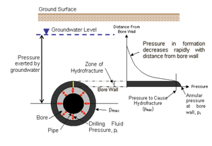
When drilling fluid pressures exceed maximum allowable pressure of the surrounding soil, localized plastic yielding of the soil surrounding the annulus occurs. The limiting radius of yielding occurs at the point where pressure is equal to the pressure required to cause plastic yielding. Beyond this zone, hydrofracture does not occur. Figure 1 shows this concept.
Localized hydrofractures — those that do not reach the surface — are typically sealed by excess groundwater and earth pressures soon after the HDD bore is completed. This healing phenomenon is supported by experience in large scale HDD tests conducted by the Corps of Engineers.
Maximum allowable calculated pressure at any point is the pressure required to create a plastic (failed) zone equal to the depth of soil above the pipeline at that point. That is, the factor of safety against the plastic zone reaching the ground surface is 1.0 for any location along the maximum allowable pressure graph. The actual factor of safety applied to a project must account for potential consequences and reliability of input parameter values used.
Minimum drilling fluid pressure required to return the soil cuttings back through the HDD bore to the surface is a critical factor in evaluating hydrofracture risk. Minimum pressure depends on the length, depth and diameter of the bore, the weight of the drilling fluid and the flow rate. Minimum required pressure is a combination of the drilling fluid head pressure that must be overcome and the frictional resistance to flow from the bore wall.
Drilling fluid pressures are often highest during the pilot bore, because of the smaller annulus and one-way flow path. During reaming, drilling fluid can flow out through the entry or exit; the annulus is larger, so pressures are usually lower. But pressures during pullback can be high, because the larger diameter of the product pipe reduces the annular flow path.
Actual drilling fluid weights vary. However, good practice dictates that drilling fluid properties, including weight, be properly managed to achieve satisfactory results. Mud weights should be maintained below 9.5 lb/gal.
Once the maximum allowable and minimum required pressures have been calculated, it is important to compare the two numbers at critical features, such as locations of low earth cover, crossings beneath utilities, beneath rivers and environmentally sensitive areas, near embankment toes or at large distances from the entry point, to get a comprehensive view of hydrofracture risk.
Drilling fluid pressures can vary greatly with the contractor’s methods and changes in ground conditions. The minimum required pressure is exactly that: a minimum. Although calculations may indicate there is little risk of hydrofracture, an inexperienced operator or unforeseen soil conditions can greatly affect that risk. Selection of an experienced, qualified contractor is an important step in preventing hydrofracture. A thorough and accurate geotechnical investigation is a pre-requisite for success. Since the results of a hydrofracture risk evaluation are so dependent on the assumptions regarding ground conditions, groundwater levels, contractor means and methods and drilling fluid properties, the evaluation should be conducted using a range of values and assumptions to bracket the limits.
If comparison of the maximum allowable pressure and the minimum required pressure indicate an unacceptable risk of hydrofracture, the design should be altered to reduce that risk. Hydrofracture risk can be reduced by altering the geometry of the bore — shortening the bore, deepening the bore or selecting better soil strata for the alignment. Conductor casings can be used to help maintain bore continuity through rocky, gravelly or loose soils near the surface so that drilling fluids don’t escape the annulus. Once the bore has passed beyond the end of the conductor casing, increased thickness and typically higher strengths of the soils help reduce hydrofracture risk. Additional risk mitigation techniques include relief wells, piezometers and monitoring.
Relief wells can be installed at locations where excessive drilling fluid pressures may exceed the soil’s capability to resist hydrofracture. Locations should be selected that are accessible for containment and cleanup equipment, making it easier to maintain a clean worksite, while avoiding damage to sensitive features.
Regardless of the preventative measures used, any project with a significant risk of hydrofracture should have a contingency plan. This plan should include a procedure for containing and cleaning up any inadvertent fluid returns and describe materials that the contractor should have on hand such as sand bags, hay bales or wattles to contain the fluid, a vac-truck or trailer, shovels, brooms, barrels to contain the fluid and submersible pumps to remove the liquid.
Hydrofracture risks can be evaluated and managed using the tools described above, coupled with experience and judgment, to allow a successful, safe project.
Dr. David Bennett, Ph.D., P.E., is president of Bennett Trenchless Engineers, Folsom, Calif.