FRP Goes Deep and Far in Minneapolis
The I-35W/I-94 tunnel system in Minneapolis, ranges in size from 8- to 14 ft in diameter and varies from 50 to 130 ft underground. Cycles of pressurization and depressurization have led to structural distress of the liner and subsequently caused erosion of the friable St. Peter sandstone in which the tunnel was constructed. As a means to restore structural integrity, an external void grouting and crack sealing program was enacted to prevent further structural damage to the tunnel.
This grouting program was successful for the most of the tunnel system, except for a segment that was experiencing high groundwater pressure, inflow and a noticeable decrease in effective liner thickness. As such, this segment of 12 ft in diameter, at approximately 100 ft below grade level, needed a structural repair. A proprietary fiber reinforced polymer (FRP) system (StifPipe) with a 3D core layer was selected by the project engineer for this point repair with high loads and limited access. The StifPipe system was installed layer by layer and cured in place with increased ambient temperature by using heaters. Another challenge the project team had to face was to complete installation in a short time period to control pumping cost. The project was completed with success without any significant issues encountered at the project site. The I-35 tunnel repair project marks a record as the deepest application of an FRP system for fully-structural tunnel rehabilitation.
The I-35W/I-94 system stormwater tunnel system ranges from 8 to 14 ft in diameter and from 50 to 130 ft in depth. It is one of the four storm water tunnel systems beneath Minneapolis. During certain storm events, the tunnel becomes surcharged to the point that access shaft covers are literally blown off by the force of water. These surcharge events also pressurize the tunnel liner, which consists of cast-in-place unreinforced concrete approximately 12 in. thick. Cycles of pressurization and depressurization have led to structural distress of the liner and subsequently caused erosion of the friable St. Peter sandstone in which the tunnel was constructed. This progressive erosional process creates voids behind the concrete liner reducing tunnel liner confinement.
As a means to improve tunnel liner structural integrity and external void grouting, a crack sealing program was enacted to prevent further structural damage to the tunnel. This grouting program was successful for the most of the tunnel system except for a segment that was experiencing high groundwater pressure, inflow, and a noticeable decrease in effective liner thickness. As the design firm of the overall project, Brierley Associates concluded that a fully-structural liner is to be used for the rehabilitation of aforementioned 20-ft tunnel segment. The tunnel is approximately 100 ft below the surface at the location of repair, and this dictates a high soil pressure factored into the design. At this depth, groundwater pressure was also tens of feet, and the project site was subjected to active leaks for an extended period of time. These leaks were stopped by a combination of dewatering and chemical grout (hydrophilic polyurethane) injection at multiple points. Pressure relief ports were also doweled into the tunnel wall to mitigate the groundwater pressure.

Composite FRP System Design
The proposed design called for a structural rehabilitation system that can be conveniently conveyed to the repair point, which is more than 100 ft below ground with the nearest access hole 3,250 ft away. As such, an FRP solution was an ideal fit with components delivered to the location of repair in boxes (fabrics) and drums (resins). Due to the high external loads, a conventional FRP system would require excessive layers of carbon fiber laminae to meet those loads for a stand-along design. As such, the more economical FRP composite StifPipe was proposed in lieu of a conventional carbon fiber only design. StifPipe system includes a proprietary core layer that eliminates the need for too many layers of carbon fiber to meet the external loads. Due to its light weight and high strength, StifPipe has a much smaller carbon footprint than the conventional materials, and in fact it has won the ASCE’s Innovation Award as “a Green-Sustainable Solution for Construction and Repair of Pipelines.”
The StifPipe system was originally developed by Ehsani based on the concept of I-beam (Ehsani, 2017). Because of this design, a much higher stiffness vs. bending (or buckling) can be achieved in a structural element by increasing its vertical dimension only. As such, the original StifPipe was made with a sandwich structure including a 3D fabric (think about a series of polymeric I-beams distributed throughout an FRP fabric in between the conventional glass and carbon fiber fabrics. This concept was tested at QuakeWrap’s R&D lab for its strength against parallel plate load (ASTM D2412).
Although, the results were impressive for a flexible FRP pipe of 37 in. ID and a total thickness of only 0.5 in., the level of stiffness was satisfactory for semi-structural rehabilitation; i.e., partially relying on the strength of the host pipe. The proof of concept was achieved, but higher performance was needed to bring StifPipe to a level of stand-alone pipe in an economical manner. As such, in second tier of experiments a new configuration was used with a custom-engineered polymeric 3D (core) fabric. This light weight, high porosity fabric can absorb a lot of resin, thereby increasing the compressive, as well as the flexural strength of the core layer. These two parameters play a major role in increasing the ring stiffness of a pipe.
The new StifPipe was tested recently with the following configuration: Four layers of biaxial glass fiber fabric (B26G); one layer of 10 mm core fabric; and two layers of uniaxial carbon fiber fabric (TU27C).
Application of StifPipe with the Wet Layup Method
Although, the first application of StifPipe goes back more than 10 years, the previous applications were installed by sliplining with prefab StifPipe segments. Approximately, two years ago QuakeWrap started to experiment installing StifPipe with the wet layup method (cured-in-place), and the first project was carried out on a 66-in. Middlesex County storm sewer pipe with success. Nevertheless, the design loads for that application were much lower than those of the I-35 tunnel project at more than 100 ft of soil cover. As such, the I-35 tunnel repair required an elaborate and extraordinary design with dual core fabric in addition to the carbon and glass fiber layers. The design was tested with mock installations at the QuakeWrap R&D lab to identify any issues that could arise due to using a relatively thick FRP system with up to a gallon of resin to saturate seven sq ft of core fabric.
I-35 Tunnel Repair
Although, the first cured-in-place (wet layup) application of StifPipe was completed in a 66-in. storm sewer without any issues encountered and ahead of schedule, the second application in a 72-in. prestressed concrete pipe for drinking water transmission was not a 100 percent smooth ride. A small area of the 3D fabric felt dry to the touch after installation with an apparent saturating resin deficiency. As such, an approximately 5-ft by 5-ft section was removed and replaced with the 3D core fabric which was weighed before and after saturation to ensure sufficient resin uptake was achieved for the required strength. Another measure taken upon the 72-in. pipe rehab experience was using ribbed rollers to saturate the core fabric. There is no resin saturating machine that can be used for the thick core fabric, but development of one is currently being entertained.
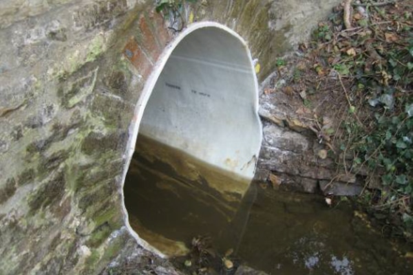
In the light of lessons learned from previous applications, and once the leaks were stopped (Figure 1) through a joint effort by the GC (PCi Roads) and Engineer (Brierley), QuakeWrap’s construction arm, FRP Construction LLC, mobilized to Minnesota for installation of StifPipe using the wet lay-up method. The access to the repair location was through a 4 by 4 ft. manhole that is more than 100 ft deep. The installation crew and materials were conveyed to the site via a skid steer ride of more than half of a mile.
The area inside the pipe was sealed-off with plastic sheets to obtain a humidity and temperature-controlled environment. Water (groundwater and small amount of snow melt) that gathered upstream at a bulkhead was pumped through the scaffolding in the repair area using bypass pipes. Moisture and temperature readings along with pull-off tests were continuously recorded during the installation process and work was overseen by inspectors from the engineering firm (Brierley) and owner (MnDOT).
The FRP Construction crew first implemented surface prep by applying a primer, and then installed the StifPipe fiber reinforced polymer (FRP) system comprised of eight layers including carbon fiber (Figure 2), glass fiber, and the proprietary 3D fabric for increased stiffness. The total thickness of the fully-structural liner was 1.47 in. Three layers of FRP were tucked into the groove cuts into the concrete tunnel liner and filled with thickened epoxy at the termination points to ensure no water would seep behind the FRP linings system.
Another challenge the project team faced was to complete installation in a short time period before the snow above ground melted and substantially increased the flows and pumping costs. The ambient temperature was 63 F; and therefore, heaters were deployed to increase the temperature to 75 F for accelerated cure. Under these circumstances, the epoxy resin used to saturate the FRP layers were dry to the touch within a couple of hours and the storm tunnel was ready to be returned to the service the next day.
After three weeks, the StifPipe installation was completed ahead of the schedule for spring rain and melting snow. The project was completed with success and without any significant issues encountered at the site.
The I-35 tunnel repair project marks a record as the deepest application of an FRP system for fully-structural pipe/tunnel rehabilitation. The StifPipe design enabled a feasible and economical solution for such high external loads and a limited access to the repair site. The components of StifPipe were easily transferred to the site in small drums (for resin) and rolls of fabric in addition to a few other miscellaneous tools and resin saturating machine.
References
Ehsani, M. (2017). ASCE Innovation Award Winner: Sandwich Construction Carbon FRP Pipe. Proceedings – ASCE Pipelines, Phoenix, Arizona.
ASTM D-2412 – Standard Test Method for Determination of External Loading Characteristics of Plastic Pipe by Parallel-Plate Loading.
V. Firat Sever, PhD, P.E., BCEE, and Mo Ehsani, PhD, P.E., S.E., are with QuakeWrap Inc., Tucson, Arizona. Tom Pullen is with Brierley Associates, Minneapolis.