Queen’s University CIPP Testing Research Update
Research at Queen’s University is using experiments and analysis to understand the strain and stress demands of pressure pipe liners across perforations in the pipe wall and joints/ring fractures.
The use of cured-in-place (CIP) liners is now routine to rehabilitate both gravity flow and pressure pipes. Research work at Queen’s University in Ontario and elsewhere on gravity flow liners has largely focused on the manner in which imperfections influence the liner’s resistance to external groundwater pressures.
Revised codes of practice and design guidelines for close-fitting liners within gravity flow pipes now address various noncircular shapes, the initial gap that generally exists between the liner and the host pipe, or initial circumferential waves in the liner caused by use of an oversized liner or intrusions that exist within the host pipe before lining, or combinations of these.
Research on pressure pipe liners is, perhaps, less developed. Ongoing studies are aimed at obtaining answers to aid the design of liners that can restore the hydraulic integrity of the pipeline. We are also examining the use of liners to maintain pipe integrity in the vicinity of construction work, over a tunneling operation for example. All these concerns lead to the following questions:
- What are the strength limit states that control the performance of pressure pipe liners?
- What stresses and strains develop in the liner where it spans across either a circular, oval or other shaped perforation in the wall of the old (e.g. cast iron) water pipe?
- What stresses and strains develop in the liner where it spans across a ring fracture or joint in the pipe being rehabilitated?
- How do ground movements imposed after lining potentially impact those stresses and strains in the vicinity of a ring fracture or joint? How do those stresses vary if the movements cause rotation of one pipe relative to the other across the joint, axial separation across the joint, or shear deformation across the joint?
- What strength limits should be considered when designing a liner for a normal rehabilitation project, and what strength limits should be considered when design a liner to maintain integrity (i.e. survive without leaking) when earthworks threaten to damage the pipeline?
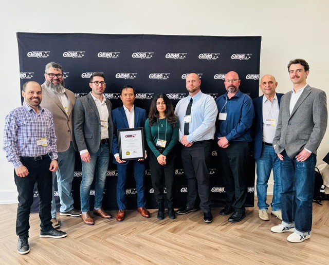
Both experimental and computational work has been under way to answer these questions (testing by doctoral student Titi Adebola and analysis by MASc student Ranlin Qiu).

Dr. Adebola (Figure 1) installed optical fibers within a series of cured-in-place pressure pipe liners, first using them to measure strain distributions where the liner crosses perforations of various sizes (Figure 2). Ranlin Qiu compared Dr Adebola’s measurements with his calculations (Figure 3), and demonstrated the effectiveness of earlier computational studies by Mike Brown (Brown et al., 2014) that explained how perforation size dictates the controlling strength limit – circumferential bending stresses on the inner surface of the liner at the boundaries of small perforations, then axial bending stresses for larger diameter perforations. The current design equation in ASTM F1216 for pressure pipe liners crossing small perforations is effective, but unfortunately the equation for liners crossing large perforations provides unsafe estimates of maximum stress and strain.

Ranlin Qiu then used his finite element analysis to examine strains where liners cross under elliptical perforations, and demonstrated that conservative estimates of peak strain and stress can generally be obtained by considering a circular perforation having a diameter equal to the largest dimension of the non-circular hole.
Dr. Adebola also used optical fibers to measure strain distributions along the inner surface of the liner where it crosses between two segments of metal host pipe (passing across a joint or ring fracture), Figure 4. Patterns of longitudinal tension develop, with yield strain of about 1.5 percent reached for these specific test conditions at a rotation angle between the two ends of the metal pipe segments of about 0.3 degrees.

Following these encouraging comparisons between measured and calculated strains, design equations based on theoretical studies undertaken with doctoral student Kejie Zhai visiting Queen’s in 2021-22 are currently being published examining the consequences of various kinds of ground movements on the liner crossing between the metal pipe segments – axial extension, rotation (like that seen in Figure 4) and shear deformations. For earthworks projects (e.g. subway tunneling) where liners are used to safeguard the integrity of overlying infrastructure such as cast iron water pipes, these new design equations can be used to estimate the strains that will develop in the liners, so the likely liner performance can be estimated.

All these research results have been published in a series of peer reviewed papers (details are available on request).
*These studies were jointly supervised with Dr. Neil Hoult, professor of structural engineering and an expert on structural health monitoring in civil engineering at Queen’s. Support was provided by the Natural Sciences and Engineering Research Council of Canada (NSERC) through a Strategic Research Grant, Discovery Grant funding and Research Tools and Instruments grants. The Cities of Hamilton, Kingston and Toronto provided support (e.g. cast iron pipe specimens) and thanks to Sanexen for assisting with pressure pipe liner installations.
Dr. Ian Moore is a professor in the Department of Civil Engineering at Queen’s University.