The Planning, Construction of Microtunneling Projects
March 3, 2017
The path to a successful microtunnel installation – or any tunnel project, for that matter – starts well before the first pipe is ever pushed into the ground. Critical components of the pre-construction phase include planning,collecting data, soil/rock testing and presentation of the geotechnical data and bidding documents. Post award, the contractor is tasked with selecting the most appropriate mictotunnel boring machine (MTBM) system, as well as slurry separation equipment, for the anticipated ground conditions.
During the construction phase, the contractor must then adhere to accepted best practices. In this article, the authors discuss some of the most critical considerations in putting a microtunneling project on the path to success.
Microtunneling Design
No microtunneling project is too small for a geotechnical data report (GDR) and a geotechnical baseline report (GBR).
Planning
The first consideration is determining the pipeline line and grade. This may sound simple, but locating the position of your pipeline requires an intimate understanding of the ground conditions, and the microtunneling equipment and its capabilities, in order to save costs and avoid problems during construction. Following is some advice in planning your line and grade:
- Seek local knowledge of past construction projects. If you can obtain previous documents from projects completed near the proposed site, you are that much ahead in getting started on planning the line and grade of your project.
- Physically establish a line of sight between shaft locations. Sometimes you can identify obstructions like a bridge support pier or sheet pile wall along the proposed tunnel route.
- Beware of existing utilities and service manhole inverts that “straddle” the tunnel route. It is not unheard of for “as built” drawings to have been incorrect by anything from 1 to 10 ft – or more. Pothole all potential interferences when feasible.
When you have a clear line and grade, then you can turn to the ground conditions. Geologic factors such as mixed face conditions could be a real challenge and should be avoided if easily solved by raising or lowering the alignment. Pay attention to the past or present uses of the project site.
Railroad embankments are notorious for being landfills containing old railroad remnants such as ties, fishplates, old rail and other deleterious materials that can stop an MTBM. Additionally, some soils in these areas contain heavy contamination that can require special handling to dispose of the muck, driving costs higher. Recognizing these potentials early and realigning the alignment to avoid them can save tremendous cost and delay.
Many times with gravity sewer lines, the design engineer decides location without collaborating with the geotechnical engineer who should be familiarized with the capabilities of a microtunneling system. Too often, we have inherited projects in which slurry microtunneling is specified and the pipeline is located less than 10 ft below the ground surface in loose, saturated silty sands or other soils susceptible to hydraulic fracturing or settlement.
Most MTBMs have the ability to counter-balance existing earth and ground water pressures (i.e., they measure the pressure being exerted on the machine and the operator sets slurry charge pressure to counter-balance the ground pressure reading).
In conditions where you have shallow or no ground water pressure readings, it becomes increasingly difficult to monitor the face pressure and counter balance it. In this situation the recommendation is the slurry charge pressure should be <0.1 bar per meter (3.28 ft) depth of cover (i.e., the equivalent of a column of water preventing the charge slurry from migrating to the surface).
Where there is shallow cover it becomes much more likely for the slurry pressure to overcome the overburden pressure resulting in hydraulic fracturing of the ground. Or, on the flip side, too little pressure is applied causing a sink hole. An easy way to reduce the potential risk of hydraulic fracturing or settlement is to provide more cover above the MTBM.
The length of individual drives and location of shafts should be preplanned to provide a cost-effective solution. Engineers can be familiar with past projects that achieved record drive lengths, some exceeding lengths of 1,500 ft or more, and tend to want to push the capabilities of the system based on these rare accomplishments.
The reality is microtunneling becomes exponentially more difficult for drive lengths exceeding about 1,700 lf. Most long drives will require the utilization of multiple interjacking stations (IJS). The process involves activating the IJS near the MTBM head, causing separation in the pipe string typically not more than about 12 in., then that separation is closed back up by the main jacking system in the shaft. Now imagine a 1,700-plus-ft drive.
It is not uncommon to have up to five IJSs in the pipe string. The process would involve this extension and closure five separate times to advance a total of 12 in. It is time-consuming and costly and it is likely that it may have been much more cost-effective to have designed the project with two 850-ft drives, perhaps with one or two IJSs.
Collecting Data (Subsurface Explorations)
It is hard to believe after all the papers and articles on preparing contract documents and geotechnical reports, some owners still are letting contracts for trenchless installations with little to no subsurface information.
Often, the owner feels covered by including contract language that the contractor is responsible for obtaining geotechnical data. The contractor, however, is not a specialist in geotechnical engineering and it is not in the benefit of the project to “pass the buck” to the contractor at the time of construction.
The contractor’s objective is to build the job as cost-effectively as possible and this arrangement can lead to deficient number and quality of test borings performed to plan the project. It is the owner’s responsibility to perform the necessary – but not an excessive – number of borings, test pits and lab tests to provide contractors with sufficient information to successfully plan, bid and build the project.
With regards to what constitutes sufficient subsurface exploration, there are many guidelines and articles in the literature. It is the authors’ preference to initially take borings at a relatively wide spacing (300 ft) then review how the subsurface data correlates while in the field and perform more borings if we are seeing a high variability in the subsurface conditions. At a minimum, for any length drive there should be borings at the launch point and reception point.
Also, borings alone are usually not the only answer for field investigations. One of the most common differing site condition claims for microtunneling projects is the encountering of nestled cobbles and boulders. Borings cannot tell you if you have cobbles and boulders, they can only provide indications.
Test pits or large diameter bucket borings are essential in ground where cobbles and boulders are suspected to exist. I recommend every subsurface exploration program include some sort of test pit or auger drilling to investigate the subsurface for cobbles and boulders if there is potential for them to exist.
Additionally, the borings and test pits need to go deep enough to extend through the pipeline grade and at least 1.5 diameters below the pipe invert so as to be aware of potential mixed face conditions or soft deposits that may cause the machine to dive.
Laboratory Testing
Standard index testing is routine and cost effective to provide the engineer reliable information. Grain size analysis with hydrometers to obtain the fraction of clay are also critical to MTBM projects in which separation equipment is utilized. Data will be utilized to determine screen sizes, number of hydrocyclones and the potential use of a centrifuge system.
If it’s a rock tunnel, then core samples must be collected recording RQD, percent recovery in the field and then performing UCS, Cerchar Abrasivity and Brazilian Tensile testing in the laboratory to understand the properties of the rock.
Geotechnical Reports (GDRs and GBRs)
No microtunneling project is too small to not warrant preparing a geotechnical data report (GDR) and a geotechnical baseline report (GBR) to be presented with the bidding documents.
Many owners and engineers are accustomed to using GDRs and GBRs on large tunneling and underground projects and may feel that level of effort is not justified for a relatively short, small-diameter utility tunnel. Don’t believe it!
The GDR-GBR format has proven to be effective to share risk and reduce claims and cost while providing a team approach that is critical for a successful project. Just because your project is $1 million compared to $100 million, there is an appropriate size GDR and GBR that can complement your project’s size, budget and condition.
Bidding Documents
When preparing drawings and specifications, the authors like to stick by the “Goldilocks” rule of thumb: Don’t do too much and don’t do too little. Overly detailed drawings and specifications which lock a contractor into a box remove the one entity that may have the best thoughts, ideas and insights on how to procure and build the project most cost-effectively. A bid package that does not leave the door open to allow contractors to exercise innovations will likely result in a more expensive project.
Conversely, if the bidding documents are silent on too many critical issues, it can lead to the same high-cost result. The owner’s engineer should have performed a review of the ground conditions and assessed the feasible excavation methodologies and offer methods that provide the highest potential for success. Not specifying the feasible methods could open the door to overly aggressive contractors that are willing to risk simpler open-face methods in highly adverse ground conditions that lend themselves to more sophisticated systems.
Microtunneling Construction
Assuming the foregoing has been adequately put in place, a microtunneling project is headed in the right direction. At this point, it is imperative to understand and interpret the information that has been presented and select the most appropriate microtunneling system to excavate the ground while maintaining optimum productivity and minimizing risk.
The authors’ approach to constructing a microtunneling project can be summarized in five stages:
Stage I – Determine if the microtunneling system has the capabilities to work at the depths and attain the drive lengths/alignments laid down in the tender documents.
Stage II – Determine the status quo of the tunnel face conditions. Do you need to win the ground, prevent in-rush or a combination of both while counter balancing ground water pressures to a greater or lesser degree? Establishing head-on conditions dictates the optimum cutterhead configuration you are looking for, i.e., rock head, open head, semi-head or a customized project specific variant. It also dictates how you manage conditioning of the slurry for face support, where required and cleansing of the slurry for optimum collection and transportation of excavated material.
Stage III – Ascertain how the excavated material will be transferred/processed from the cutterhead usually via a crusher to the slurry chamber of the MTBM. Lack of understanding of this digestion process can lead to projected expectations/returns being greatly diminished. It also becomes a finite point in MTBM selection as this is an area where there are subtle but significant variants between manufacturers.
Stage IV – Define the size range/volumes of processed materials being delivered to the slurry chamber for collection by the charge slurry medium and return transportation as discharge slurry for remote separation.
Establishing volumes of particles >3mm, >70µm and potentially and more importantly <70µm dictate slurry separation plant requirements, e.g. primary conveyor units, secondary de-sander with hydro-cyclones units and tertiary centrifuge plants with flocculation dosing units.
It would not be unfair to state that the evolution of slurry separation equipment/techniques in the microtunneling industry has been a “slow starter.” More to the point it is more appropriately viewed as the “runt of the litter” especially when you consider the propensity of past tendencies to dump residual slurry into drains and sewers or into waterways and replenish with clean water.
Nowadays greater awareness and regulatory controls dictate this is no longer acceptable and techniques have developed to the point where competent microtunneling practitioners prescribe having suitable separation as a pre-requisite. This is also backed up by the “math”:
- If optimum slurry for the prevailing ground conditions is not delivered to the MTBM, it cannot collect 100 percent of the excavated material, which effectively “chokes” the machine and reduces progress.
- Downtime incurred, trucking away contaminated slurry and replenishing with clean water is lost production time.
- Generally you will incur costs for trucking away/replenishing services.
- Pumping inadequately cleansed slurry through the microtunneling system unnecessarily increases equipment wear and tear.
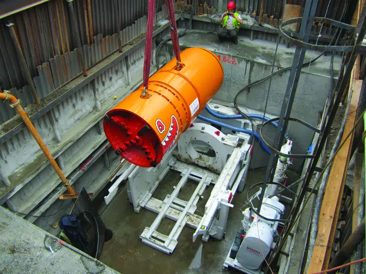
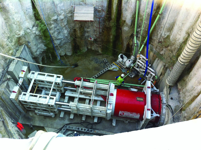
Stage V – Understand the requirements of producing safe working and receiving shafts for launching and recovering the MTBM.
Shaft construction methods are many and varied with selection often taking into consideration locally available materials, techniques and proficiencies. However, the primary driver is dealing with ground water conditions and providing a safe working environment within these “temporary works” structures.
Shafts should be capable of withstanding pre-determined jacking loads required to propel the MTBM over the tunnel drive length and facilitate safe entry into the ground and exit out of the ground. Never forget launch/recovery of the MTBM are generally recognized as the most difficult aspects of microtunneling and once in the ground operations become relatively straight forward.Pay particular attention to:
- Drive shaft thrust wall loading requirements including ground stabilization where required.
- Drive and reception shaft head wall sealing requirements.
- Entrance and exit gland seal arrangements with potential built in redundancy.
- Prevention of MTBM/tunnel line thrust back.
- Drive shaft/reception shaft ground stabilization requirements for MTBM launch/recovery.
- Safety, dewatering, gas monitoring, safe entry and emergency egress.
An engineered risk reduction approach along with properly prescribed jacking pipes and annulus lubrication regime should result in a successful conclusion for the project.
Todd M. Kilduff, P.E., is a consulting engineer with Kilduff Underground Engineering Inc., and Paul Wilkinson is a consulting engineer with WLK Micro Services and former general manager for Iseki Euro.