Installation at Los Alamos National Laboratory Showcases New HDD Technologies
December 13, 2012
Kelly Utility Services of Albuquerque, N.M., was subcontracted to install the 18-in. (45.7-cm) HDPE pipe that will serve as a conduit for radioactive liquid waste (RLW) for the Chemistry and Metallurgy Research Replacement Project at Los Alamos National Laboratory (LANL). Because the HDPE will contain two RLW lines, the LANL technical representatives emphasized the need to ensure that the pipe was not compromised during installation. Given these concerns, Kevin Campbell of Kelly Utility Services contacted Digital Control Inc. (DCI) for assistance. DCI makes the DigiTrak line of locating equipment for the horizontal directional drilling (HDD) industry.
LANL is located in New Mexico at an elevation of 7,323 ft above sea level on a plateau created by the Valles Caldera eruption more than 1 million years ago. LANL employs approximately 11,000 individuals who perform strategic research for the U.S. government. The soil consists primarily of compacted volcanic ash known as tufa rock. LANL is most noted for the completion of the Manhattan Project, which developed and constructed the atomic bombs that ended the war with Japan in WWII.
 HDD technology was selected as the construction method for this project due to the number of existing below-ground utilities. In an effort to ensure that there was no disruption to these utilities and to provide detailed information on the pilot hole, a DigiTrak Fluid Pressure Transmitter (FPT) was selected for use. Additionally, in an effort to prevent excessive force on the HDPE during installation, a DigiTrak F5 TensiTrak Pullback and Pressure Monitoring System was used with a DigiTrak F5 locating system. This combination of equipment, along with a DigiTrak Log-While-Drilling (LWD) PC software, provided an accurate as-built of the bore, the annular drilling fluid pressure and the pull force data. This is the first time these new technologies have been used together to complete a project.
 After conducting a background interference check to determine the optimal operating frequency, the dual-frequency 19/12 FPT was selected for use in 19.2-kHz mode.
Kelly Utility Services used a Vermeer 80 x 100 drill rig with a Vermeer 300 reclaimer system for the project. Kelly did not want to disclose its tooling selection for competitive reasons; however, it did disclose a mud mixture using CETCO’s HYDRAUL-EZ product with a 45 viscosity rating for drilling in the tufa formation.
The project was not without complications. During potholing of utilities, an industrial waste line was located proximal to the bore path. A bore profile redesign was required that resulted in changing the planned location of the second vault. Modifying the plan took two days and signatures from six LANL engineers and managers. Another complication was cold weather. The temperatures on the Los Alamos plateau were in the teens Fahrenheit overnight during most of the three-week project, requiring daily thawing of the reclaimer pumps and piping.
The pilot bore required one lateral turn and a compound curve to allow connection to the two 16-ft (4.9 m) deep vaults that would be installed post HDPE installation.
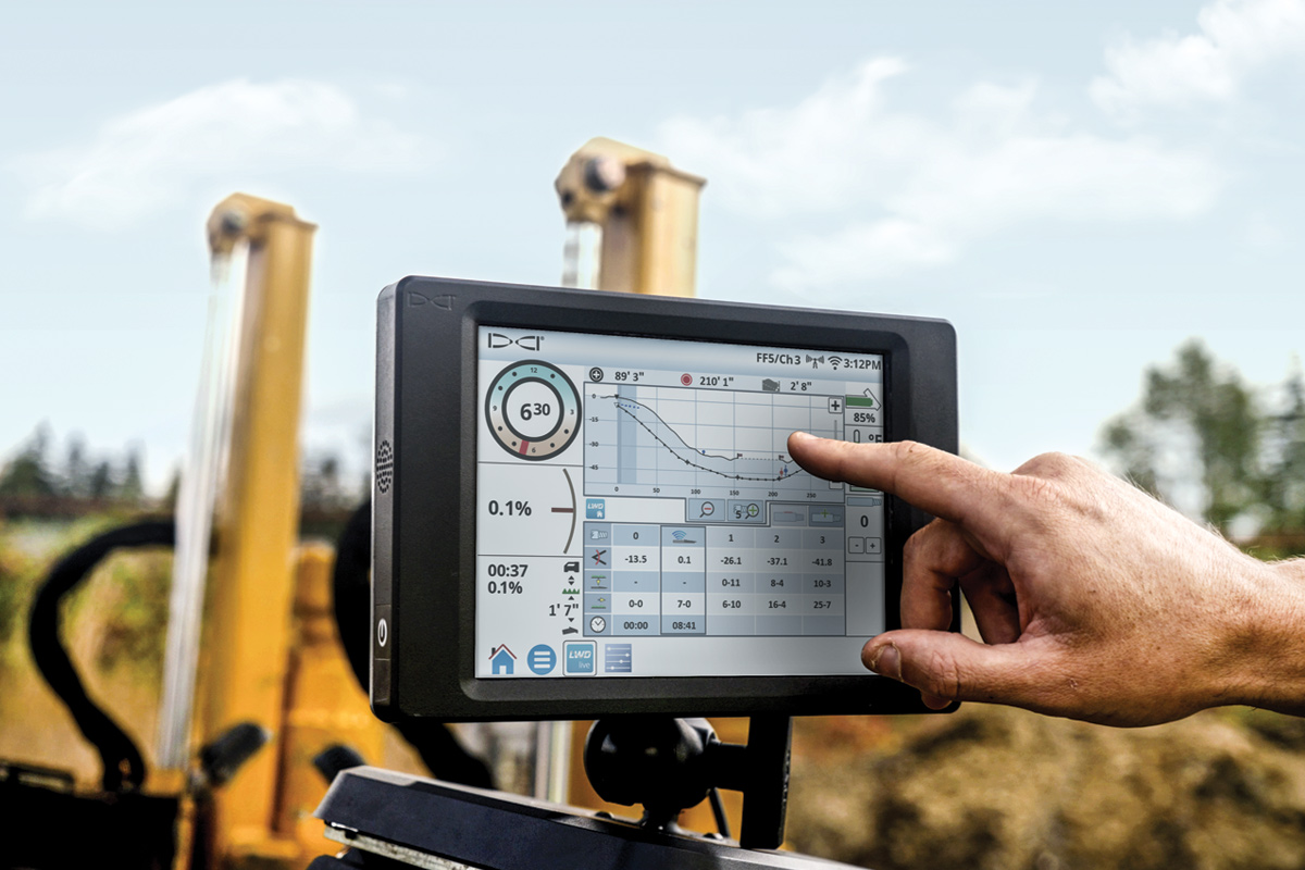
The LANL technical representatives were keen on seeing an as-built of this project. Figure 1 below shows the profile and pressure charts for the installation, recorded using the F5 locating system and documented in the LWD software program.
 The upper chart provides the as-built of the bore, topography, and plotted utility and marker locations. The lower chart shows the annular drilling fluid pressure measured during the pilot bore. As the topography shows, there was a continuous gentle rise in elevation and then a sharp decline near the exit pit, where the topography dropped nearly 25 ft (7.6 m). This wall face did not allow walkover locating. Up to the cliff edge, standard locating functions were used by Kelly’s locator, Ken Howell. Once the drill head’s location at the top of the rise was recorded, the F5 receiver was placed at the bottom of the wall face on the exit pit edge and was set up for use with DCI’s Target Steering function. The Target Steering capability allows the F5 receiver to be programmed with a target depth and positioned ahead of the tool, as a target, transmitting steering information to the drill operator’s display. Utilizing the Target Steering technique, Kelly’s drill operator, Erasamo Agurirre, was then able to steer the tool into the exit pit, 2 ft (61 cm) below an existing storm drain and on target.
 Figure 2 shows the site with the 18-in. (45.7-cm) HDPE pipe staged and ready for installation. Due to the limited lay down area an additional section of HDPE had to be welded and allowed to cool once the pullback began.

The 720-ft length of HDPE pipe was welded using a McElroy TracStar. The HDPE had a manufacturer-specified maximum pull force of 75,377 lbf. LANL engineers were concerned about the installation of this pipe because it would act as the conduit for two RLW lines. Therefore, exceeding the pipe manufacturer’s maximum rating was not an option.
The TensiTrak tension monitoring system was used to monitor and record the pullback data. The tension monitor is connected between the reamer and the pipe being pulled in and, therefore, only measures the load applied to the product pipe. This allows the drill rig operator to monitor in real time the pull force on the pipe and the annular fluid pressure. The advantage of tension information is that corrections can be made right away during the installation to prevent damage to the pipe.
The pull force and annular fluid pressure were measured continuously during pullback and then uploaded to a laptop equipped with DigiTrak LWD™ software via a Bluetooth connection.
The pressure and tension charts shown in Figure 3 read from right to left, where the pilot exit pit (beginning of pullback) is on the right and the drill rig is on the left. There are four occurrences that depict notable changes in pressure and force. The first occurrence (1) is when the final section of pipe was fused and allowed to cool during the early portion of the pullback. The second occurrence (2) is near the first vault location at the compound curve, which resulted in notable force and pressure increases as expected. Rod rack changes occurred at (3) and (4).
The maximum force applied to the product during this installation was 42,240 lbf, well below the aforementioned maximum manufacturer’s installation rating of 75,377 lbf. LANL was assured that the pipe was not compromised during installation because of the information Kelly Utility Services was able to provide using a DigiTrak F5 system with the Fluid Pressure Transmitter, the TensiTrak pressure and tension monitor and the LWD software.
Joe Jadwin is an engineering quality manager at Digital Control Inc. (DCI).


Comments are closed here.