How To Microtunnel Through Karstic Rock
Over the past 40 years, the microtunneling method has grown into one of the more reliable tools for installing utility tunnels in the United States. Owners and engineers value its applicability in diverse and varying geotechnical formations, as it can prove to be the proper solution from both raveling sands to massive rock, and mixed conditions in between.
However, if there is a downside to this diverse applicability, it is that the method has in part become the victim of its own success, as expectations of what can be reliably accomplished have risen significantly in the engineering community. There are geotechnical formations where constraints may limit microtunneling as much as any other trenchless method.
Karstic rock is such a formation, for while it can be successfully microtunneled, it presents a significant and unique risk profile.
What Is Karst?
Karst is a landscape defined by the dissolution of soluble rocks, such as limestone, within which random voids, caverns or streams may be both present and undetectable by common geotechnical exploration techniques. Numerous risks are created by this condition for microtunneling.
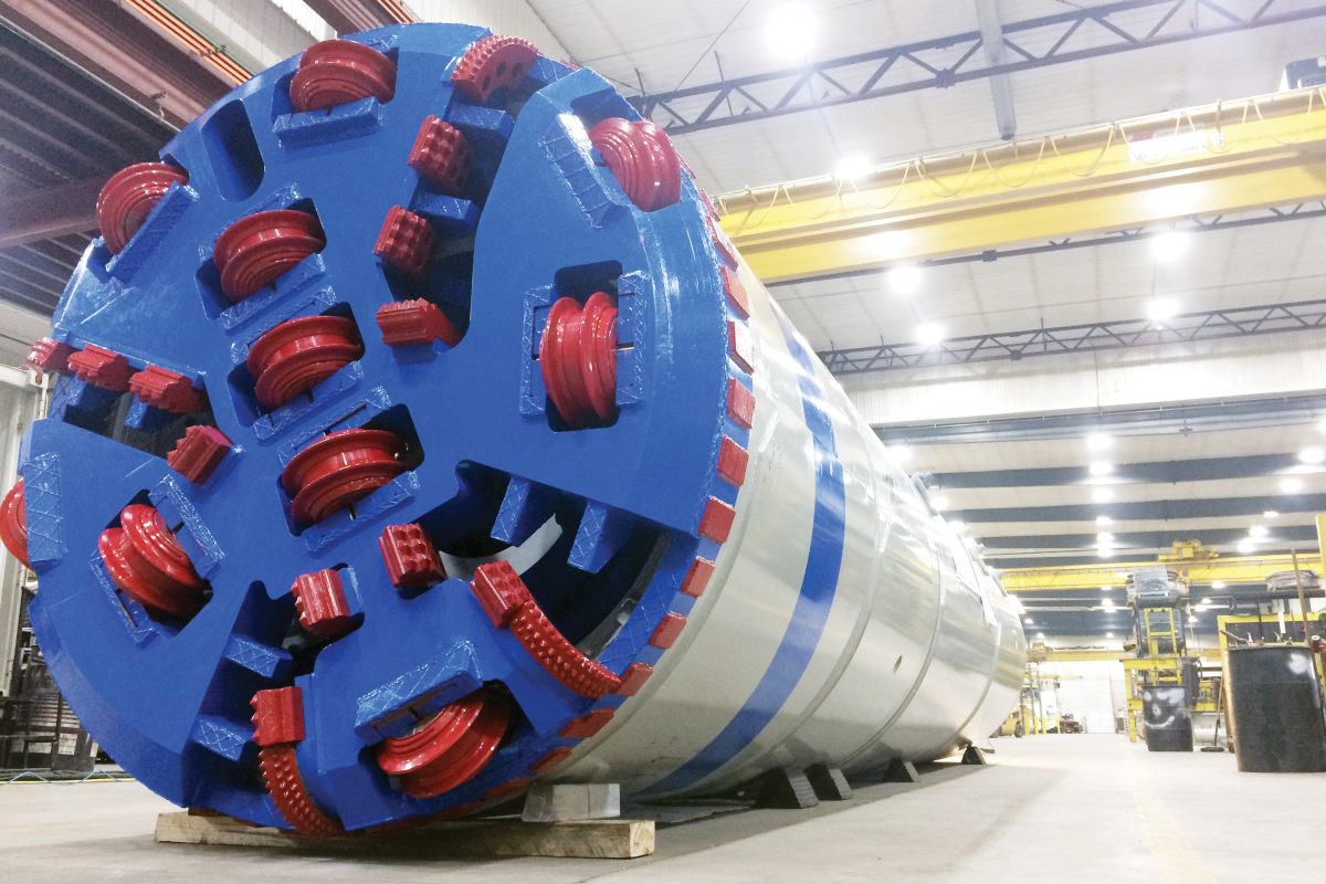
Significant voids or caverns might not support the microtunnel boring machine (MTBM). Minor instances might result in steering/friction challenges, and extreme cases could even result in complete MTBM detachment from the pipe string.
A continuous void, cavern or stream could result in unmanageable slurry loss. Attempting to grout voids encountered during tunneling operations could create additional risk as well.
How can a contractor know the extent of a void? How can they assure that the MTBM or pipe string won’t become grouted into place?
And lastly, while soluble rock like limestone may not be overly abrasive, face access for cutter tool changes must be available.
How can cutter tools be changed if the MTBM is stuck within a continuous, high flowing water source?
All of this is not to suggest that tunnels cannot be installed within karstic rock.
As with any tunneling project, risk management parameters must be implemented to provide the best chances for success. Karst rock requires extensive pre-planning, but even more importantly, it requires adaptability by the project team to manage the changing conditions as they present themselves.
Microtunneling in Karstic Rock
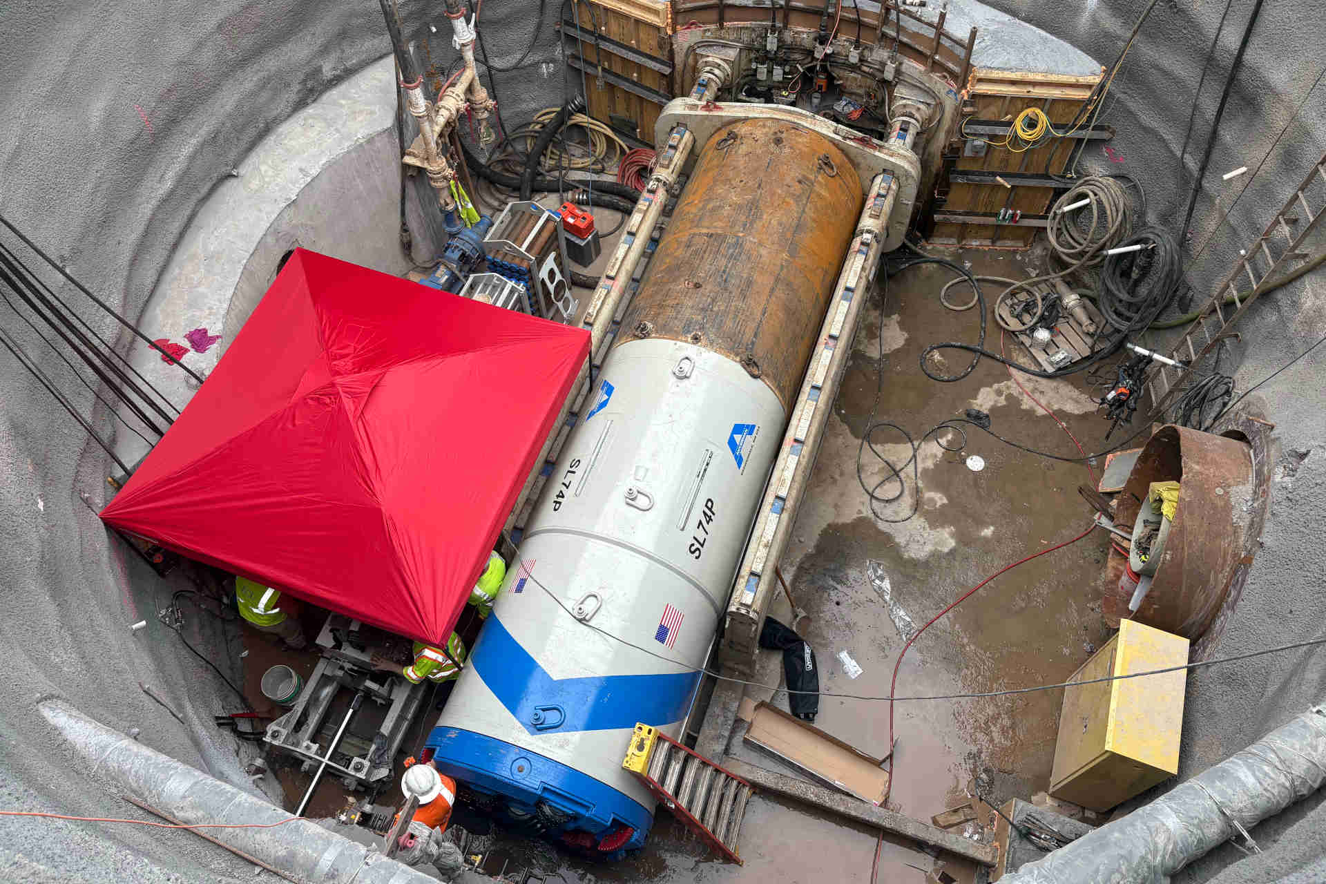
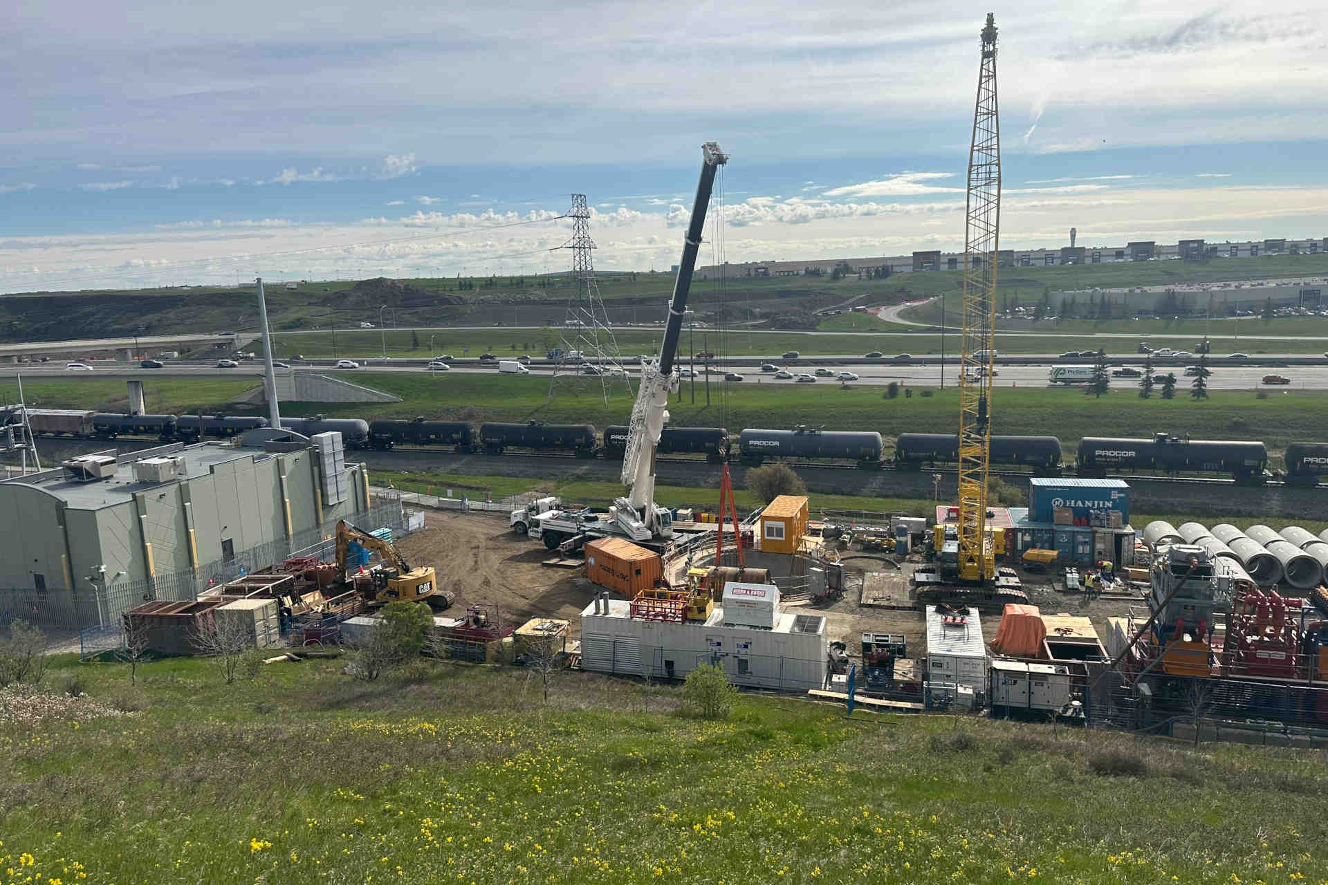
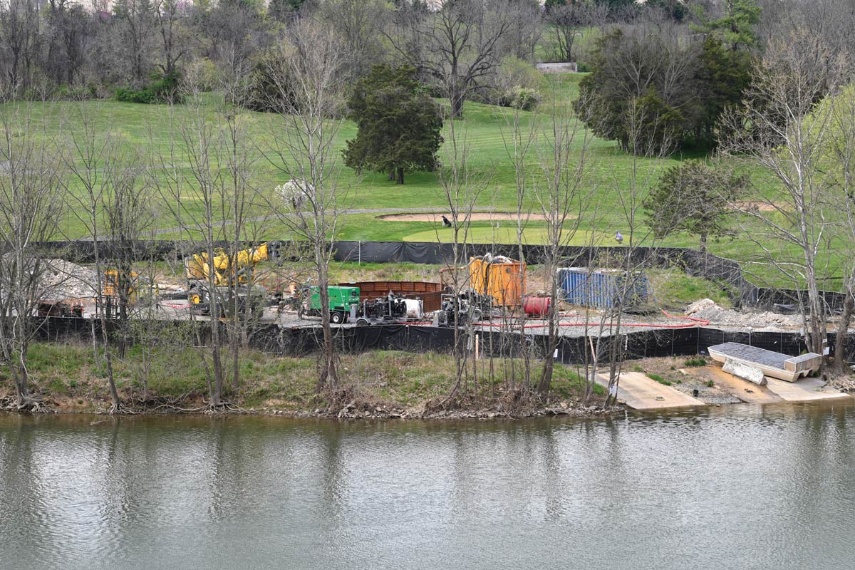
Bradshaw Construction Corp. recently completed a project in karst conditions on the Parallel Waterline for the Route 522 North Corridor project in Front Royal, Virginia.
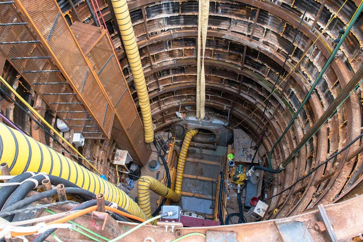
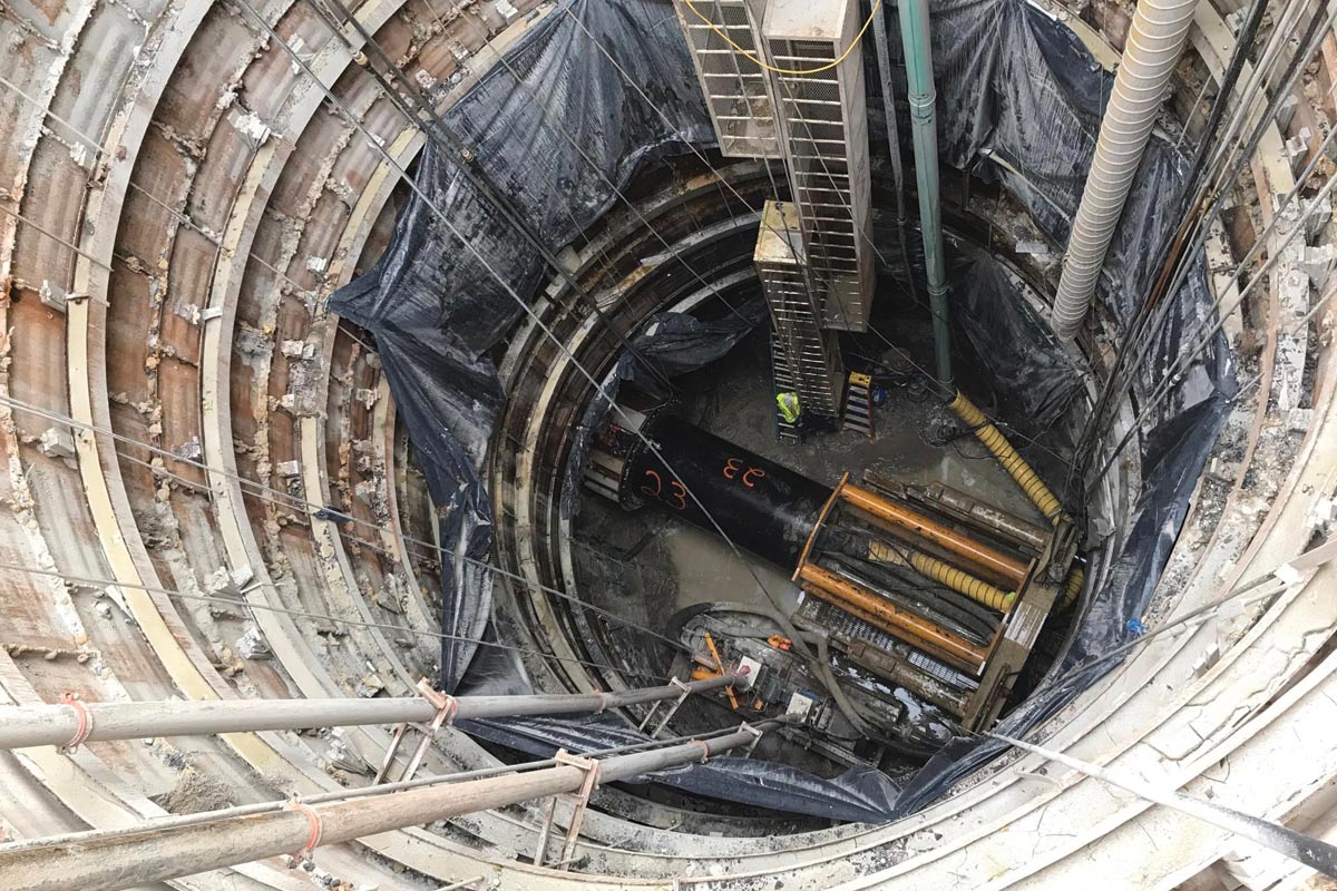
The project involved the construction of a 60-in. diameter, 555 lf tunnel to be installed underneath the Shenandoah River. The tunnel would be constructed out of and into two liner plate shafts, 49 and 57 vf deep.
Geotechnical investigations for the 555-ft tunnel alignment included four soil borings/rock cores, laboratory testing, and an electrical resistivity imaging (ERI) scan to measure potential karst features.
The four borings showed 15 to 25 ft of limestone coverage above the crown of tunnel, with each boring showing 100/100 recovery/RQD for at least 5 ft above tunnel crown, indicating no karstic conditions at the boring locations. Laboratory testing showed unconfined compressive strength results in the 15ksi – 20ksi range, and Cerchar abrasivity readings in the 1 – 3 range, indicating massive rock with medium abrasivity.
However, the ERI scan indicated that while much of the alignment would be in competent and consistent bedrock, subsurface irregularities may be present on the southern (receiving) side of the alignment, indicative of potential karstic rock conditions.
During the installation of the launching pit, the shaft installation contractor quickly encountered significant water inflows, suggesting potential karst voids on the launch shaft side as well.
The shaft was pre-blasted, and the deeper the excavation reached, the higher the water pumping requirements became. By the time the launch shaft was excavated, roughly 4,000 GPM was being continuously pumped and discharged.
Three significant seams each approximately 1 ft in diameter were identified near subgrade, with high flows showing direct communication with the Shenandoah River, and with more seams potentially unobservable below subgrade.
Adaptation Is Key
It was determined that tunneling operations would instead need to be launched from the southern side, where water inflows had been limited and manageable during shaft excavation.
Despite challenging access issues and a smaller design, the receiving shaft was able to be safely blasted and “belled out” at tunnel elevation to allow for recessing the pipe jacking equipment and allow for installing the tunnel casing without any groundwater inflows.
The challenge would now be to successfully navigate a rock tunnel through any potential karst conditions beyond those referenced in the contract documents, a likely scenario given the launch shaft seams.
Previous microtunneling experiences in limestone with comparable characteristics had yielded daily production in the 15- to 20-ft range, with cutter interventions being needed every 100 to 200 ft. With the possibility of hitting karst conditions and communication with the Shenandoah River, safely managing MTBM face interventions would be essential.
When properly administered in rock, polyurethane grouts can be utilized to temporarily fill the tunnel annulus and seal off water inflows to the MTBM face for cutter changes, without consequential impacts on pipe-string friction. However, the real risk would be if the cutters failed within a void or active water communication zone, with no ability to advance the MTBM past the zone and no access to change the tooling.
Completing the Work
As such, conservative mining parameters were planned and implemented. These parameters turned out to be essential. Cutter wear occurred more frequently than previously observed in comparable rock. Instead of three planned interventions to change 14 total cutters, 10 interventions were needed to change 47 cutters.
Two significant seams were encountered, corresponding with minimal slurry communication with the river and direct river communication to the tunnel. Because cutters were being regularly inspected and replaced, the MTBM was able to advance past these seams to allow for properly sealing the annulus with polyurethane grout, limiting inflows to the face.
Production was slower than anticipated, with the tunnel taking twice as long to install as planned, but successfully installing the tunnel on line and grade through the high-risk karst conditions was worth the unanticipated impacts.
Karstic rock is undoubtedly a high-risk formation for tunneling, but sometimes there are few good options when charting the path for new utility installations.
However, recognition of these unique risk factors can improve the expectations for owners and engineers and potentially help shape contractual risk sharing on future projects.
Meanwhile, contractors will best position themselves for success by engaging in an adaptive approach to tunneling through karstic conditions.
Jordan Bradshaw is a project manager at Bradshaw Construction.