Guidelines for Use of Mini-Horizontal Directional Drilling for Placement of HDPE Pipe
January 1, 2011
 A set of guidelines for the use of mini-horizontal directional drilling (mini-HDD) has recently been developed by the Plastics Pipe Institute. Technical Report TR-46, Guidelines for Use of Mini-Horizontal Directional Drilling for Placement of High Density Polyethylene Pipe, represents a comprehensive set of information supporting the placement of HDPE pipe by mini-HDD equipment.
 The new document is intended to provide information analogous to that provided in ASTM F 1962, Standard Guide for Use of Maxi-Horizontal Directional Drilling for Placement of Polyethylene Pipe or Conduit Under Obstacles, Including River Crossings, but at a level appropriate for the less complex mini-HDD technology and typical project characteristics.
ASTM F 1962 provides overall guidelines, addressing preliminary site investigation, safety and environmental considerations, regulations and damage prevention, borepath layout and design, implementation and inspection and site cleanup for maxi-HDD operations. One of the significant contributions of ASTM F 1962 is the provision of a rational, analytical method for selecting the polyethylene pipe strength based upon the estimated installation and post-installation (operational) loads on the polyethylene pipe. However, while considered convenient and practical to apply by experienced engineers for a maxi-HDD operation, the equations and procedures provided in ASTM F 1962 represent relatively complicated formulae and an extensive tedious methodology, when considering smaller, lower cost operations associated with typical mini-HDD applications.
Mini-HDD operations are often performed during an upgrade of a large community, comprising many individual installations, with any single installation not requiring or receiving extensive analysis. Nonetheless, some mini-HDD installations may be considered to be relatively critical or approach limits with respect to the capability of the available drill rig and/or the strength of the product pipe being installed. Furthermore, any construction procedure must address basic safety rules, avoid damage to existing facilities, adhere to applicable government regulations and consider environmental issues.
TR-46, Guidelines for Use of Mini-Horizontal Directional Drilling for Placement of High Density Polyethylene Pipe, was developed to serve as an inclusive document, providing practices for placement of HDPE pipe using mini-HDD. It is anticipated that TR-46 will become widely used for mini-HDD pipeline installations, serving a similar role as ASTM F 1962 for maxi-HDD applications.
Description of TR-46
Technical Report TR-46 comprises 10 main sections, plus six Appendices and References:
- Scope
- Referenced Standards and Specifications
- Terminology
- Preliminary Site Investigation
- Safety and Environmental Considerations
- Regulations and Damage Prevention
- Pipe Design and Selection Considerations
- Bore Path Planning and Drill Rig Setup
- Implementation
- Completion
- Appendices (A – F)
- References
The scope includes the design, selection considerations and installation procedures for the placement of HDPE or conduit below ground using mini-HDD equipment. It is beyond the scope of the TR-46 guidelines to provide detailed operational procedures for the various mini-HDD and auxiliary equipment. It is assumed that the contractor has gained the appropriate proficiency. Applications include the placement of pipelines for conveying fluids, such as water, natural gas and oil, as well as ducts or conduits for containing communications (telephone, CATV, etc.) or electric power supply cables. TR-46 reflects the latest industry information, but also includes new information not readily available elsewhere. For example, guidelines are provided for proper drill rig positioning, consistent with meeting required placement depths and drill rod capabilities, in an easy to use, convenient format. Of particular interest is a practical methodology for estimating the relevant forces and effects present during installation, based on the route geometry, facilitating proper selection of the pipe wall thickness.
Pipe Design and Selection Considerations
 In comparison to ASTM F 1962, TR-46 contains a convenient calculation method appropriate for persons with various backgrounds, including the operators of mini-HDD equipment and/or the utility engineers. In particular, the procedure presented provides a means of selecting the pipe strength to avoid collapse due to hydrostatic pressure at the desired placement depth, as well as to withstand the required pulling loads during installation. The pipe strength is directly related to the wall thickness, as specified by its dimension ratio (DR) defined as the pipe outer diameter by the (minimum) wall thickness. The methodology is based upon a simplification of ASTM F 1962.
Minimum Wall Thickness Based upon Depth
The guidelines indicate that essentially all the commonly used wall thicknesses (e.g., DR 7.3 to DR 17) for HDPE pipe would be sufficiently strong for depths to approximately 15 ft, the typical limit for mini-HDD installations. These depths assume an empty pipe during the installation and pre-operational phase, in the absence of internal fluids or pressure, which would offset the effects of the external pressure due to drilling fluid/slurry. For depths greater than 15 ft, thinner wall pipe, or special situations, the adequacy of the product for the application should be verified using the information provided in the appropriate appendix.
Minimum Wall Thickness Based upon Pulling Load
The following equation was developed as a convenient means of estimating the peak force applied to the pipe as it is pulled throughout the bore hole:
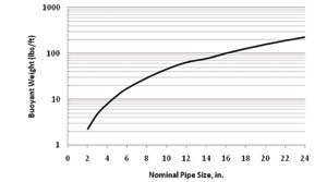
Tension (lbs) = [Bore Length (ft) x Buoyant Weight (lbs/ft) x (1/3)] x (1.6)n
The recommended buoyant weight may be conveniently selected from Figure 1.
The parameter n is equal to the number (or fraction) of 90-degree route bends due to cumulative route curvature, where n = n1 + n2. The quantity n1 is the effective number of deliberate/planned 90-degree route bends, and n2 is the cumulative curvature (90-degree route bends) due to the unplanned undulations. The following value of n2 is suggested:
n2 = [Bore Length (ft) / 500 ft] x [2-in / Rod Diameter (in.)]
The criteria for selecting an appropriate pipe strength then corresponds to selecting a DR value with a safe pull tension at least as large as the estimated tension, as determined above. (TR-46 provides a table of safe pull strengths for various pipe sizes and DR values.) The mini-HDD calculations generally result in considerably shorter possible placement distances than that corresponding to application of the methodology and equations provided in ASTM F 1962, which may also include the use of anti-buoyancy techniques to reduce buoyant weight to significantly reduce required pull loads. The shorter placement distances for mini-HDD are also due to the increased drag (“capstan effect”) generated by the additional route curvature of mini-HDD operations, due to path corrections, which are typically of greater magnitude and significance than that encountered in well-controlled maxi-HDD installations. In general, other methods for determining pulling loads, including available software tools, are typically based on well-controlled maxi-HDD installations and not representative of actual mini-HDD applications with respect to anticipated pull loads.
Bore Path Planning & Drill Rig Setup
TR-46 addresses the planning of the borepath, consistent with meeting the requirements of the project owner, including placement depth and also provides corresponding drill rig setup information.
 Figure 2 illustrates a typical mini-HDD bore vertical profile trajectory, including occasional pits along the route. These pits may be required for pipe splicing, completing lateral connections or to expose existing utilities. Figure 2 designates certain points along the bore path and their relative distances from the drill rod entry or exit points. These distances are a function of the entry angle and drill rod characteristics (e.g., allowable radius of curvature, or “bend radius”), and determine the setup location and space requirements in which to perform and complete the pipe installation. For pipe constructed from HDPE, the bend radius limitation of the drill rods is sufficiently large to be compatible with that of the product pipe.
Figure 3 shows a typical plot for the required setback distance of the drill rig corresponding to the distances shown in Figure 2, and also indicates the minimum possible depth for a level trajectory.
Although the TR-46 guidelines are primarily described with respect to mini-HDD operations, the information may also be applicable to midi-HDD installations. Thus, guidelines for the use of midi-HDD machines and associated practices may be obtained from the present TR-46 document, as described herein, and/or ASTM F 1962, depending upon the particular application and the judgment of the contractor or engineer.
Dr. Lawrence M. Slavin is president of Outside Plant Consulting Services Inc., serving the telecommunications, power and pipeline industries. For a copy of the guidelines: http://plasticpipe.org/pdf/tr-46-hdd-guidelines.pdf.