A ‘Wireline’ Bore In Heavy Interference — Without A Wire
Northern Pipeline (NPL) is a nationally recognized infrastructure construction company headquartered in Tucson, Arizona, with almost 50 years of experience installing utilities, much of it in later years employing trenchless technology methods.

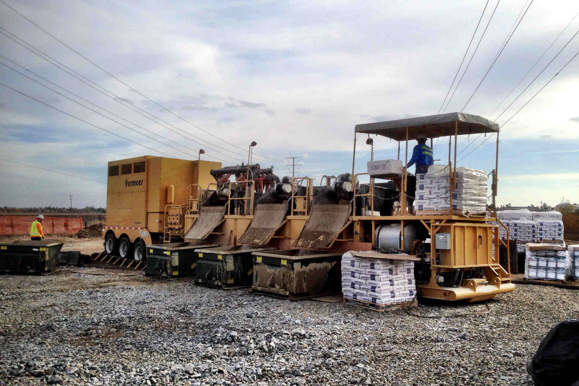
The pilot bore started at 8 a.m. on April 20, 2016, using a Vermeer D330x500 drill and the DigiTrak Falcon F5 locating system.
In April 2016, NPL was working for Nipsco, a provider of gas and electrical services, to install a 24-in. gas main in Munster, Indiana. This was one of four planned HDD bores and called for a 1,000-ft bore to be installed at a maximum depth of 28 ft. It would cross the intersection of Indianapolis Boulevard and Ridge Road at its deepest point.
RELATED: HDD Contractor Tests DCI’s Newest Locating System in Texas
Planning the Bore
In the planning stages of the bore, NPL assumed this would be a difficult one. This was not due to the sand and clay ground conditions, which most drillers would call good, but because of the required depth and the likely presence of extreme interference. NPL bore superintendent Kurt Eberly was planning to use a wireline guidance system, which is NPL’s typical solution for bores like this. This decision was further verified when a few weeks prior to the bore Eberly used one of its DigiTrak F5 systems to perform a range test. This highly recommended step allows a contractor to see what they will be up against from an interference standpoint and to gauge locator performance.
NPL brought one of its classic F5 receivers and a dual frequency transmitter into the intersection, the deepest point of the bore, and moved the transmitter away from the receiver, simulating the separation with the transmitter in the ground. They tested both of the transmitter’s frequencies (12 and 19 kHz) and in both cases, roll and pitch data was lost at 12 ft, verifying that the maximum bore depth of 28 ft was far beyond the 65 ft the system was rated to provide in a non-interference environment. The interference was primarily caused by large overhead powerlines, other buried utilities, and traffic light sensors.
Interference
Interference in the context of HDD locating is classified as active or passive. Active interference is often defined as “anything that emits a signal or generates its own magnetic field” while passive interference can be described as “anything that blocks, absorbs, or distorts a magnetic field.” On this particular installation, active interference was the primary obstacle.
Active interference emits a signal that competes with the transmitter’s signal. This, in turn, can reduce the receiver’s ability to accurately pick up the transmitter signal. Some of the effects of active interference include erratic signal strength and depth readings, impaired depth readings (depths may appear less than they actually are), loss of pitch and roll data, and inaccurate receiver calibration (which may lead to depth errors).
Dealing with Interference
There are typically three primary methods of dealing with interference. The first is to try to achieve separation between the receiver and the interfering source. For example, moving to the other side of the bore path where roll and pitch signal reception might be better. In the middle of the intersection, this proved unsuccessful as data was lost at a relatively short distance.
RELATED: Drill Master: Interference & HDD Locating Systems
A second method is to use a different frequency, as many locating systems support more than one. The success of an alternative frequency depends primarily on how close it is to that of the interfering signal. In NPL’s pre-bore test, two of the F5 receiver’s five frequencies yielded far less range than was required.
A third method is to resort to a more powerful (stronger signal) transmitter. Here, the assumption is that a stronger signal stands a better chance at reaching the receiver over the interfering sources. The ability to boost transmitter power is inherently limited by the size and design of the transmitter and the power source (battery). In some cases, interference is so strong that no amount of power boost can overcome it.
Another “extreme” option, wireline guidance, transmits steering information up a wire and is therefore generally not affected by outside active interference. But this option is expensive and time-consuming as wire connections have to be made for each drill rod, adding significant time and dozens of potential wire splice failures to the pilot bore process.

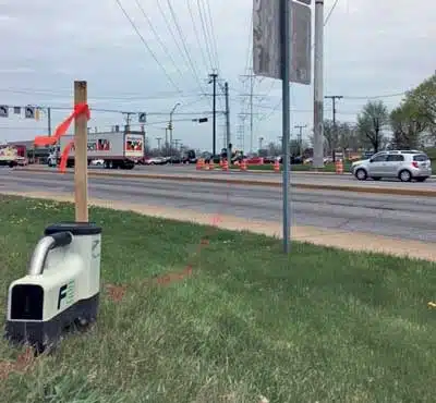
The proposed bore path crossed under the intersection of Indianapolis Boulevard and Ridge Road.
Falcon Technology
In early 2016, DCI released a new technology — Falcon — aimed directly at combatting active interference. Falcon technology allows a user to measure active interference at a job site, identify one or more optimum bands of multiple frequencies, and pair these bands with a transmitter. In short, Falcon adapts to the different interference characteristics at every jobsite in a way that systems using a few discrete frequencies cannot.
Falcon technology divides the roughly 40kHz-wide operating range (4.5 to 45 kHz) into nine bands, each band spanning 4.5 kHz. This wide range encompasses most of the discrete frequencies used in today’s walkover systems. The bands are identified by their approximate center frequency: 7, 11, 16, 20, 25, 29, 34, 38, and 43. This simplifies the user interaction as well as communications related to frequencies.
The user selects which band to use based on readings from the receiver’s frequency optimization menu (in general, this is the band with the lowest amount of active interference, with exceptions for the visible presence of passive interference such as rebar). Within the selected band, the system uses multiple specific frequencies customized for that site. Falcon F2 and Falcon F5 also allow the operator to optimize and select a second band to use where interference requirements change. An operator might optimize and use one band for most of the bore and the other in an area of high interference, without having to trip out.
Checking Interference with the Falcon F2 System
Once the Falcon technology became available, Eberly contacted Julian Perez, Midwest manager for Digital Control and Matt Lind, sales for Vermeer Aurora, Illinois, to find out whether this new technology might do better than their current system. Completing the job with a walkover system would mean significant cost and time savings.
Lind brought out a Falcon F2 system and after turning on the frequency optimizer (FO), walked and scanned the entire 1,000 ft of intended bore for interference. It became clear that the center of the intersection at the planned 28-ft depth was also where interference was the heaviest.
RELATED: Drilling in Hard Rock in Northern Virginia
One of Nipsco’s project requirements was to document the pilot bore, which Nipsco needed to see before NPL was allowed to proceed with the pullback. This required the Falcon F5, which includes Log-While-Drilling (LWD, or data logging) as a standard feature.
Drilling the Pilot Bore
Although above-ground range testing with the Falcon was encouraging, NPL had a steering tool service on standby in case of any issues.
At the point of highest interference in the intersection, Lind ran the Falcon F5 frequency optimizer to identify the best frequencies for this particular area. The FO showed that the optimal frequencies to overcome the high interference here were neither 12 nor 19 khz (tried with the classic F5) but rather frequencies within the 39-47 KHz range (band 43). Testing above-ground range with band 43 (separating the transmitter from the receiver, where the F5 lost signal at 12 ft.) showed it could achieve a distance (depth) of 42 ft. This test convinced Eberly that this pilot bore could be completed using a walkover system.

NPL continued to use the Falcon system on three additional bores where a walkover system would not have been considered in the past.
Lind performed a second optimization at another point along the bore where high interference was present from power lines overhead and utilities underground. Range testing there showed more than enough to meet the planned depth of 21 ft using band 34.
With both bands selected, he then paired the Falcon F5 receiver and transmitter, which transfers the receiver’s optimized band data to the transmitter via Infrared (IR) communications in a few seconds.
The pilot bore started at 8 a.m. on April 20 using a Vermeer D330x500 drill and the DigiTrak Falcon F5 locating system. The pilot bore took a total of 13 drilling hours to finish. Roll/pitch loss was a major concern due to exact pitch parameters allowed for each rod per the bore plan, but all the above-ground range testing proved to be accurate: at no point throughout the bore were roll or pitch lost. The pilot bore was logged using the LWD feature of the Falcon F5 and within minutes of completion, an LWD Log file containing the bore profile and rod-by-rod details had been sent to Nipsco for its approval before starting the pullback.
Due to the success of this high-profile bore completed with the Falcon F5 walkover system, NPL continued to use the Falcon system on three additional bores where a walkover system would not have been considered in the past. On one of the bores NPL used a more powerful 19-in. Falcon transmitter that increased the already impressive 15-in. Falcon transmitter’s depth capability of 100 ft by 30 percent.
The Future of HDD
Because a system specified to a certain depth in ideal conditions may not always meet that specification in the presence of active interference, the ability to choose the frequencies that work best with the interference at a specific jobsite becomes a critical advantage over other systems. With its unique method of scanning interference and selecting multiple optimal frequencies for individual jobsites, a Falcon guidance system comes closer to getting every job done than any other system.
According to Eberly, NPL saved about five days of setup time by not having to survey and place a grid needed for the wireline system. During the pilot bore, they realized further time savings by not having to perform wire splices required on each rod for wireline systems.