Remediation Beneath California Tank Farm:
September 21, 2011
 Horizontal directional drilling has long been established as a viable, even preferred, technology for installing remediation wells at many contaminated sites. Wells have been installed beneath factories, railroads, roadways, rivers and lakes, and residential areas — a variety of locations where vertical wells or trenching either isn’t possible or disrupts ongoing site activities too much to consider. As the technology has matured, longer and more complex bores are being undertaken, with outstanding results.
In 2007, Directed Technologies Drilling (DTD) installed a single groundwater extraction well down gradient from a 90-acre tank farm at a defense site in Southern California, part of a pilot project to determine how well such a system would work to remove contamination resulting from fuel that had leaked from storage tanks at the facility. Two years later, after extensive testing had documented the effectiveness of the technology, DTD was called again to design and construct a much larger installation to capture groundwater beneath an adjacent 40-acre tank facility, with aboveground storage tanks more than 200 ft in diameter and active construction of new tanks under way.
“This is typical of environmental projects,” recalls DTD president Dan Ombalski. “These projects have long lead times, sometimes measured in years, since designs and negotiations with environmental protection agencies at the state and federal levels tend to be complex. Permitting, materials acquisition and mobilization all take a lot of time and effort, as well. You don’t just drive onsite and start drilling.”
The first well installed at the site in 2007 was 880 ft long, 35 ft deep and was constructed of 4-in. stainless steel well screen and casing. The installation had many challenges. As with many environmental projects, there was limited engineering emphasis on the horizontal well installation. Typical environmental well specifications, including this one, include only a single entry location, the position of the well screen and a requirement for the well to function in capturing contamination. This leaves the responsibility of the design on environmental boring contractor, who frequently needs to complete the bore planning with relatively sparse field data.
In 2010, with a substantially increased scope of work, the new project was pushing the boundaries of environmental projects previously approached using HDD. The four new wells were more than 100 ft deep, ranging from 1,100 to 1,800 ft in length. The 6-in. stainless steel well screens and casings were stiffer and heavier than previously installed 4-in. pipe. The designs were also more complicated, including compound vertical and horizontal curves that were necessary to access the contaminated zones while still enabling access to the well ends for pump installation, surface connections, and maintenance. For some wells, the entry and exits were at different elevations, which required careful management of drilling fluids at both ends of the bore.
After many project site visits to finalize launch and exit pit locations and visualize the bore path, DTD mobilized to the site in November 2010. From the site visits, it was obvious that navigation would be a problem — the compound curves, combined with lack of surface access to the bore path and the well depth, meant that walkover or even surface-coil based navigation systems would not be viable options. DTD contracted SlimDril International, to manage the navigation for the bores, using a Drillguide gyroscopic steering tool (GST). This tool, based on optical gyroscopes adapted from ballistic missile guidance system technology, is capable of extreme accuracy and does not require any surface access. However, even the Drillguide system is sometimes susceptible to outside interference, and a previous effort at the fueling depot did have some difficulties. Having worked closely with SlimDril before on several other projects, the team had confidence that any potential problems could be overcome.
DTD drilling supervisor James Ditto, comments, “These long environmental well installations really increase the complexity for steering. Drilling with the GST requires detailed survey and design data, and most designers for environmental wells don’t yet supply that information up front. Following the design is critical, since the wells are optimized to work at a certain depth — miss your path and the well may not work as planned.”
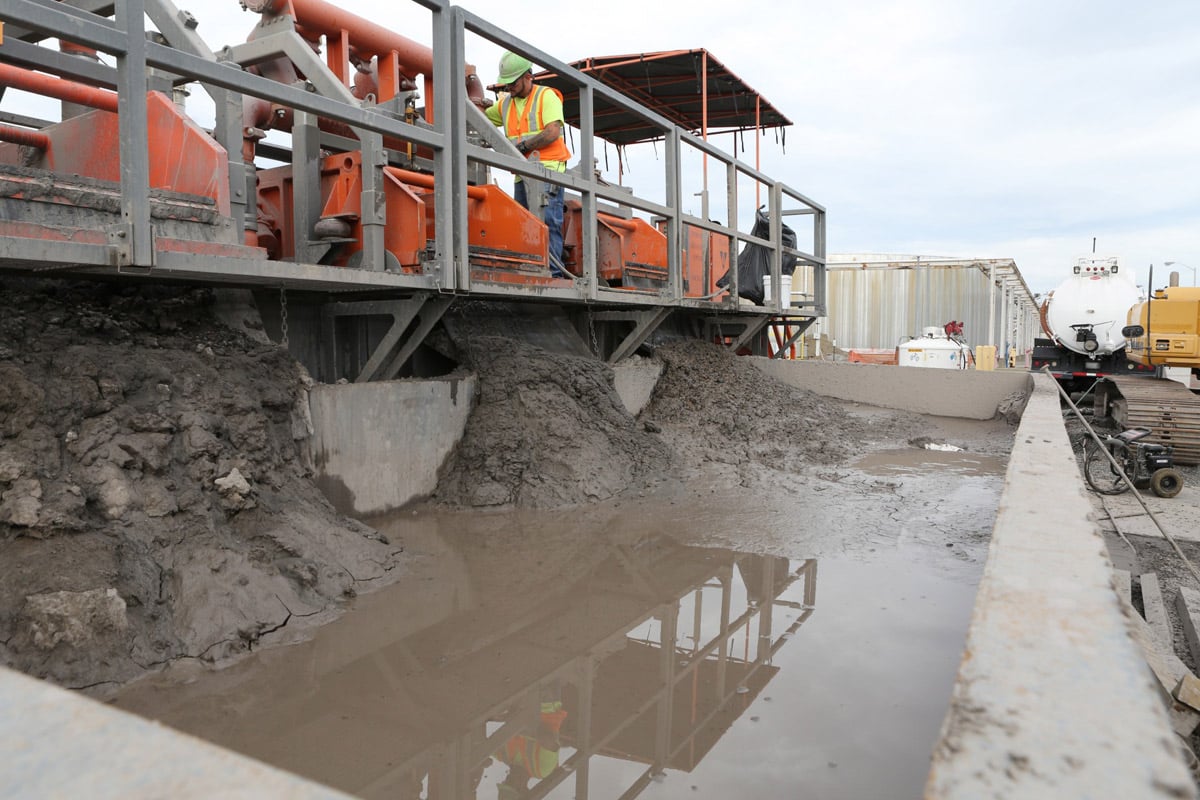
Drilling started in December 2010, using DTD’s American Augers DD210 rig. The long, double-ended bores would require considerable mud logistics, particularly when the exit was reached and it was necessary to capture and shuttle mud back to the entry. For this reason, DTD mobilized its large Mud Technology International MCT-800 mud recycler. Additional equipment included a backhoe, Gradall, and excavator. DTD provided an experienced environmental drilling crew of up to eight drillers, equipment operators, and helpers, all trained for hazardous materials operations. The DTD team was managed in the field by one of its licensed geologists, who had many years of experience in designing and managing environmental projects.
SlimDril also provided an operator for the DrillGuide steering tool. Even with the advanced Drillguide navigation system, steering and navigation were complicated by numerous tanks, fuel pipelines, water lines, and 480v power lines in the exit areas.
As noted, the stainless steel well screen and casing used in the project was considerably stiffer than the HDPE pipe typically used in such an installation. For pullback, DTD used as many as two extended reach forklifts and an excavator to control the casing, ensuring worker safety and preventing damage to the well screen. Due to the layout of the exit pits and the pipe assembly/laydown area, a conventional roller system would not have been sufficient to control the pipe.
Pullback was a labor-intensive process, with four to six crewmembers manning the heavy equipment to control the well screen and managing drilling mud return at the exit end. Rig-side, the driller and two helpers handled rod pullback and removal, with other crewmembers managing drilling fluid. The entire operation required continuous coordination between the exit and rig side teams to avoid potential safety issues to crew members, or damage to the pipe. Pullback for each well was accomplished in a continuous operation, taking approximately one day per well.
 For environmental projects, the installation of the pipe does not complete the drilling contractor’s responsibilities. Following pullback, a DTD well development crew introduced additives to the biodegradable drilling mud to break it down, then followed a carefully designed development plan to clear the well screen of any impacted bore wall materials, a common problem when bore wall material is smeared into the screen slots during pullback. The development plan included pumping several well volumes of groundwater, until water turbidity stabilized.
The final construction step was to finish the well ends. A cement bentonite grout was injected into the annulus between the closed well casing and the borehole at each end, to prevent surface water infiltration down the borehole. A bentonite surface seal was installed at the top ends of each well to provide further protection, and DTD installed vaults at each end of the well to protect the well casing ends and their connection to the surface components of the water treatment system.
Michael D. Lubrecht, LG, is senior geologist at Directed Technologies Drillings. Inc.