Optimizing Complex HDD Design and Overcoming Subsurface Challenges
The boundaries of horizontal directional drilling (HDD) continue to expand, as the industry eyes longer, larger and deeper crossings. Technological advancements in drilling equipment, downhole tools, drilling fluid additives and steering systems are making yesterday’s infeasibility today’s reality. These advances have increased demands on the design and planning of complex crossings, requiring an integrated project team and risk-based design practices. Below are several tips to aid owners and design professionals with their next challenging HDD project.
Maximize The Value of Your Geotechnical Program
Not all geotechnical programs are created equal, and increasing the program’s budget and testing doesn’t always equate to better information. For complex crossings, the geotechnical team should be engaged during route planning/selection and integrated into the design team.
The first step is to develop a geological model of the crossing to support the preliminary design and to set the framework for the field program.
This starts with a thorough desktop review to identity the anticipated subsurface conditions, terrain and geohazard constraints, information gaps and potential geohazard risks. This should include review of LiDAR data, regional and local geological records, available reports and local construction case studies.
The geotechnical field investigation should be custom tailored to the anticipated geological and hydrogeological conditions. A few of the considerations include:
- The number, location and target depth of boreholes — chosen based on known data gaps and complexity of the local geology. Borehole depths should extend below the proposed bore path, allowing for flexibility in design.
- Samples are important — when gravel deposits are anticipated along the drill profile, sonic borehole drilling equipment provides continuous bulk collection of samples and leads to a better understanding of the gravel content and grain size distribution, information key for assessing feasibility and developing the design and execution plans (e.g., borehole profile, need for/length of conductor casing(s), viable zones for an intersect).
- When HDD geometry offers a large net elevation change between entry and exit, groundwater data can be critical for design and construction planning, and the installation of wells and/or vibrating wire piezometers is recommended. A net difference in hydrostatic head across the drill path, presence of artesian aquifers, or underground flow channels (drill breaks) can lead to challenges including flooding at entry/exit, mobile sand aquifers, bore destabilization, and drilling fluid dilution/pressure control. Management of active water production during execution could be very costly and is best avoided/minimized during design.
- Pairing the borehole program with a geophysical survey can help to develop a more complete geological model and identify anomalies between borehole locations. The type of geophysical survey methods and grid density should be chosen based on the anticipated geology, and the results correlated with borehole data.
HDD Design Considerations Alignment and Profile
Design of an HDD crossing typically commences by determining a preferred alignment for the crossing. Considerations include geometry of the right-of-way/easement, feature(s) to be crossed, presence of existing aboveground and buried utilities, environmental/cultural features, and adequate accessible work areas at the entry and exit locations. A straight alignment is preferred to minimize complexity and risk of the installation; however, a horizontal bend can be incorporated if dictated by project constraints or if it benefits the overall design. Drilling is commonly performed from low elevation (entry) to high elevation (exit) to facilitate drilling fluid circulation (i.e., drilling fluid flows back to the rig). The designer should attempt to minimize the elevation difference between the entry and exit points to avoid extensive length of the borehole above the rig’s elevation to be unsupported by drilling fluids, particularly in soft/loose formations.
The profile of the crossing presents another key design decision, incorporating considerations such as local topography, geology, hydrogeology, and geometrical constraints associated with the drilling equipment and/or the pipeline product. A classic HDD profile design consists of a tangent followed by a vertical curve section on either side of the crossing, which are connected by a bottom tangent. Ideally, most of the borehole is placed within formation(s) favorable for HDD operations. The length of the bore within zones such as gravel/cobble seams, transition zones above layers of bedrock characterized by boulders/large cobbles and pockets of saturated sand, should be minimized, if they cannot be avoided altogether. The minimum bending radii of the curved sections are governed by the mechanical properties and diameter of the pipe, minimum bending radii of the drill pipe (in the case of thermoplastic pipe/conduit), and considerations associated with the downhole tooling (e.g., mud motors).
Minimum depth of cover considerations includes minimum clearance from existing utilities, foundations, surface infrastructure, and bodies of water, but usually is governed by the outcome of a hydrofracture analysis to determine the depth of cover needed to prevent inadvertent returns to surface. A commonly used method is the Delft model, which considers the geostatic pressure and shear strength of the soil to determine the minimum depth of cover needed to contain the slurry circulation pressure along the length of the borehole. Though a proven and tested design approach, the designer should be mindful of local variability of geological formations, and an adequate factor of safety (typically between 1.5 and 2) should be incorporated.
Entry and exit angles are controlled by the mechanical capabilities of the equipment (typically between 8- and 18-degrees) and the rate at which borehole depth needs to be gained or reduced to maintain minimum cover. Another consideration for the exit angle is the desire to minimize the lift height of the pipe product during line pull (e.g., large diameter steel pipes require multiple cranes to maintain minimum bending radii as pipe enters the ground).
Some designers attempt to eliminate the bottom tangent to accommodate site constraints or reduce the overall length of the crossing. It is important to note that a bottom tangent provides the steering hand with an opportunity to make any needed corrections prior to engaging the ascending curved section of the bore, making it easier to stay within design tolerances, especially in hard formations. The bottom tangent is also the preferred location for placing a pilot bore intersect zone, needed not only for long bores but also for bores where surface casings are required on both sides of the crossing.
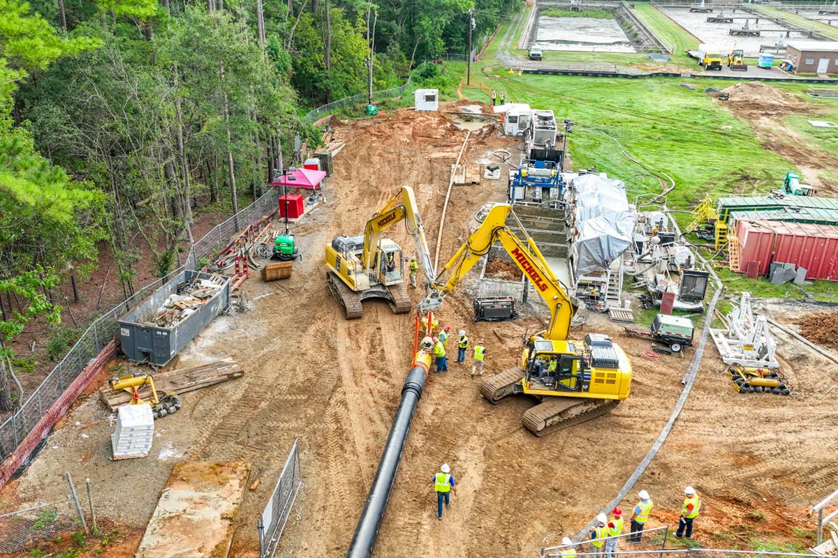
Staging Areas/Drag Section
The staging area at entry should be of sufficient size to accommodate the HDD rig, power unit, high pressure pumps, slurry separation plant, and ancillary equipment and materials, as well as sufficient space for material management (e.g., hydrovacs, water tanker, etc.). The area needed at exit is typically smaller, housing an excavator, a winch unit, or an exit rig. Additionally, a staging area is required behind the exit location for assembly of the pipeline drag section prior to line pull. As a rule of thumb, it is preferred to assemble the pipeline/conduit(s) in a single string, to avoid stoppages during line pull. If impractical due to site constraints, the number of drag sections should be kept to a minimum, to avoid introducing significant risk to the installation.
Pipe Stress Analysis
A pipe stress analysis is performed based on either ASTM F1962 for thermoplastic pipe or PRCI’s Manual PR-277-144507-R01 for steel pipe. The pipe stress analysis for HDD checks several conditions of failure and compares them against the factor of safety. The failure modes checked include short-term installation forces such as unconstrained buckling, bending and tensile stresses, as well as the long-term considerations such as excess pipe deflection and long-term buckling. Results of this analysis dictate the minimum wall thickness required for the pipe. Another parameter calculated is the minimum pull force required during line pull. Calculations typically consider surface and borehole drag forces, borehole geometry, the pipe’s mechanical properties, and buoyancy of the pipe in the borehole. Calculations are commonly reported with and without buoyancy control measures and help determine the minimum size of drill rig required for completing the crossing.
Should a significant amount of soil be expected to be added or removed from the surface above the pipe following the HDD installation, strain from settlement or heave should be considered. Also, if the alignment passes under sensitive infrastructure such as a building, a bridge, or a railway, a settlement analysis might be warranted. Several methods of settlement analysis are available based on the criticality of the application, ranging from simplistic closed-form equations based on a Gaussian distribution curve settlement profile over the pipe, to complex, multi-stage time dependent finite element models.
Other design considerations include installing a surface casing at the entry and/or exit location to create a stable, watertight corridor through shallow layer(s) of loose coarse granulates or extremely soft formation(s), minimum separation distance from infrastructure elements due to vibrations, and noise mitigation.
Summary
As technological improvements and ever-growing needs of project owners keep pushing the boundaries of HDD technology, an integrated team, detailed subsurface information, diligent design, and risk-based planning are key for ensuring the success of complex HDD crossings.
Erez Allouche, PhD, P.Eng is Tunneling and Trenchless Technology Leader at Stantec. Matthew Devitt, P.Eng, is a Senior Civil Engineer at Stantec. Carrie Murray, M.Eng., P.Eng, is a Geotechnical Engineer and Trenchless Specialist at Stantec. Patrick Doyle, P.Eng., PMP, is the Western Canada Geotechnical Practice Leader at Stantec.