Force Main Condition Assessment Using Electromagnetic Through-Transmission NDT
Force main (FM) pipelines made of cast iron, ductile iron or steel are subject to internal and/or external corrosion as soon as the pipelines are constructed. Even though the pipe may be internally lined and protected externally by coating and/or wrapping, corrosion can occur if the lining, coating or wrapping is damaged by the construction process or service conditions.
One type of corrosion mechanism that is common in cast or ductile iron pipes used in force main lines is graphitic corrosion, which leaches the iron from the pipe wall and leaves behind the non-ferromagnetic graphite matrix. The graphite stays tightly adhered to the pipe wall (inside and/or outside surface) and can only be removed by sandblasting or a chipping hammer. Graphitic corrosion weakens the pipe by reducing its local and global mechanical strength.
One particular type of corrosion in force mains is hydrogen sulfide (H2S) attack. H2S that exists in the form of gas pockets can accumulate in high spots in the FM when the FM is not 100 percent full of liquid sewage. When the pockets of H2S gas stay at these locations for prolonged period of time without being released into the air, pipe corrosion can start. Even though air release valves are often in place to release H2S, the practice of releasing H2S is often not implemented due to the rotten egg smell that members of the public can complain about. The gas pockets may remain at some locations along the FM line for an extended period of time. H2S attack starts with the gas attacking the internal lining (if there is any lining). Then the actual pipe material is attacked by the H2S. H2S attack is different from graphitic corrosion in ductile or cast iron pipes in that the corrosion product associated with graphitic corrosion may still stay in place in or on the pipe wall while the H2S attack removes healthy pipe material.
Early detection of H2S damage can help asset managers make informed decisions on maintaining the FM lines. Several varieties of non-destructive testing (NDT) techniques are available for FM line inspection, including Broad Band Electromagnetic (BBEM) and Magnetic Flux Leakage (MFL). A new NDT technique, with improved coverage and sensitivity for FM line inspection, is introduced here.

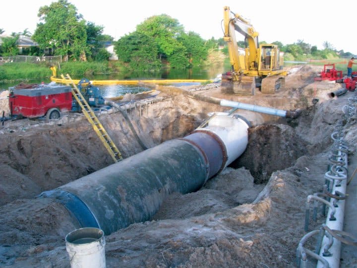
Figure 1: The Bracelet Probe being scanned on a 30-in. force main near an air release valve.
The Bracelet Probe Technology
The new NDT technique is based on electromagnetic through transmission (TT) phenomenon and the probe is called Bracelet Probe (BP). A second-generation Bracelet Probe is shown in Figure 1 where it is being scanned along a 30-in. force main pipe. The probe is an external inspection tool and can inspect pipes with a diameter range of 6 to 144 in. and sometime more due to its flexibility. The pipe material that can be inspected by the BP includes cast/ductile iron and steel pipes. The probe can detect both internal and external wall loss, including pits, local and general wall loss. Each scan covers a circumferential swath of 9 to 10 in. when the probe is scanned axially along a pipe. The scan speed is determined by pipe material type and wall thickness.
In order to facilitate Bracelet Probe inspection of buried pipelines, the segment of a pipeline is excavated to provide inspection access to the pipe. The pipe surface does not have to be smooth or super clean for the probe. Loose surface clay and mud should be removed; however, any coatings can be left in place without interfering with the inspection. Internal liner and transported product are usually non-ferromagnetic and therefore do not affect the operation of the Bracelet Probe.
The full circumference of the pipe can be inspected with multiple axial scans along and around the pipe; however, for H2S attack it is often only necessary to expose the top half of the pipe, where the expected worst corrosion can occur. Field technicians mark up the datum (0-in. reference mark) and the axial scan paths on the pipe exterior surface. The BP scan starts from the datum and finishes at the target distance. The BP data can be analyzed onsite immediately and any indications of internal or external defects can be verified by visual confirmation for the external indications and by UT (Ultrasonic Testing) for internal indications.
One advantage of the BP technique is that the inspector can pinpoint problem areas quickly and efficiently in comparison with other available NDT scanning techniques. The other advantages include minimal surface preparation, no interruption to pipeline operation, speed of inspection and price.
Application to FM Line Inspection
The BP has recently been used for condition assessment at ten excavations of a 30-in. force main. Inspection result for one segment is shown in Figure 2. The color map on the left side of Figure 2 shows areas with significant internal wall loss. The inspection covered one quarter of the pipe circumference centered at the pipe crown area. The wall loss was primarily on the crown area and extended towards the spring line, which was consistent with the characteristics of H2S attack. The other sign of internal wall loss is the existence of internal pitting indications within the GWL indications. The pipe exterior surface was in good condition without any significant corrosion.

Figure 2: Inspection results for a segment of force main pipe.
Ductile iron pipes have intrinsic wall thickness variation along the pipe length due to manufacturing tolerance. The BP can detect wall thickness variations as small as 5 percent. In a similar manor, any general wall loss caused by the H2S damage can be detected if the general wall loss is 5 percent or more. However, it is sometimes challenging to distinguish between the wall thickness variations from manufacturing tolerance and the general wall loss caused by the H2S attack unless complementary information is available, or the H2S attack is severe enough to go beyond manufacturing tolerances. The complementary information includes:
- Past inspections of the same pipe segment;
- Wall thickness information on the crown area vs. spring line areas and invert;
- Internal pitting indications within the general wall loss area;
- Internal video inspection of the areas of concern;
- AUT (Automatic UT) scanning of the areas of interest;
- Nautilus (Acoustic Sphere manufactured by Aganova and marketed by PICA) or Smart Ball leak detection scan (acoustic device manufactured and marketed by Pure Technologies).
The wall loss in the segment of pipe shown in Figure-2 was confirmed by ultrasonic thickness gauge to be 50 percent remaining wall.
Summary
As a new non-destructive testing technique based on the electromagnetic TT physical phenomenon, the BP had been demonstrated to be useful for inspection of FM lines subject to H2S damage. Any corrosion mechanism that results in an equivalent wall loss above the threshold of detection can also be detected by the BP, such as graphitic corrosion.
Dave Russell is the founder and president of PICA: Pipeline Inspection and Condition Analysis Corp., and its parent company, Russell NDE Systems, Inc. Dr. “Doc” Yuwu Yu graduated from the University of Alabama with a Ph.D. in physics and has worked with Russell NDE Systems Inc., for more than 15 years.