How to Apply ASCE MOP 145 to Gravity Lining Projects
Based on the ASCE 2025 Report Card and numerous other sources, the need to rehabilitate sewer infrastructure in North America, in a cost-effective manner with minimal impact on the public, has never been greater. By far, the most innovative technology to do this has been the evolution of close-fit flexible liners, the most common technology being cured-in-place pipe (CIPP).
CIPP, invented in the United Kingdom by Eric Wood in 1971 made its first appearance in North America in Fresno, California in 1976. Like many other innovative technologies over the years structural design for the liner did not evolve until long after the original invention.
Aggarwal and Cooper’s 1 empirical work enabled Insituform Technologies Limited (ITL) to develop the first recognized design approach for their “new” close-fit lining class in their 1983 Design Manual. Over the 1980s, the ITL Design Manual evolved into ASTM F1216 (1989), which, with very little alteration over the years, is still common in use in North America for circular host pipes.
Non-circular pipe relining in both the UK and North America was typically designed using the methods outlined by the UK’s Water Research Council (WRc) and the work of Glennie 2 for egg- and ovoid-shaped pipe.
By the early 2000s, global practitioners such as Gumbel 3 and Thépot 4 noted serious limitations with both ASTM F1216 and WRc design methods. Researchers had demonstrated the empirical models used were divergent from the true load’s and structural resistance of close-fit liners in both circular and non-circular host pipes. While often overly conservative, they could be considerably less conservative especially in larger, higher consequence installations.
ASCE MOP 145
The final North American synopsis of this was documented by the 2007 ASCE PINS Committee5, which eventually led to the development and 2021 release of ASCE MOP 1456.
ASCE MOP 145 has greatly improved the accuracy of design, especially for complex shapes, composite materials and for installations that desire to use the full technical envelop of technology. With increased accuracy comes increased complexity in the design and ASCE MOP 145’s robust nature has many moving parts that present unique challenges and opportunities for all parties in the design and construction process.
Design Process
While in theory, the equations in MOP 145 can be calculated manually, the shear number of computations requires a robust computational platform, ideally a platform that facilitates sensitivity analysis to more fully understand the accuracy to which various input parameters impact design. From a practical perspective, there is an increased dependence on digital tools to perform iterative designs for engineers to apply the standard and clearly communicate the results.
The Four-Step Process
- Define the host pipe (its geometry, and condition/design state including imperfections).
- Determine factored loads effects (including hydrostatic stress, earth and live load transfer, bending moments, hoop force and stresses and strains including the potential effect of deferred ovality).
- Determine the factored structural resistance of the liner (short- and long-term critical buckling pressure, design strength and serviceability limits).
- Check all relevant limit states for the application.
From a practical perspective, the only aspect that has an increase in complexity over conventional liner design is the definition of host pipe geometry for non-circular applications (how many of us know the radii in egg- or arch-shaped pipe?) and the characterization of imperfections.
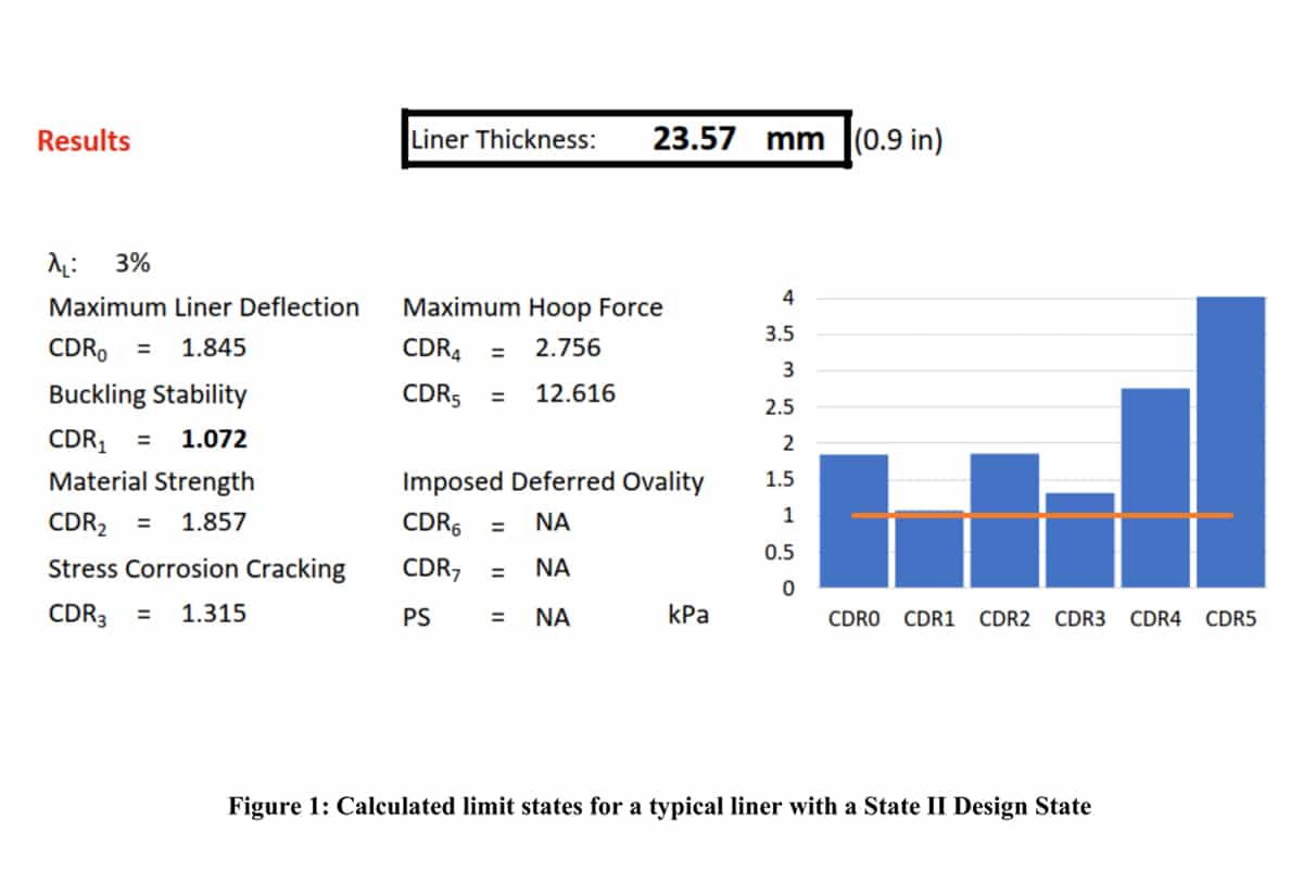
While complex computationally, the results of any MOP 145 assessment can be presented in a clear and concise format that is easy to interpret. The minimum wall thickness is calculated, and each limit state can be presented in terms of a Capacity-Demand Ratio (CDR) as noted in Figure 1.
As MOP 145 uses LFRD design methods, the CDR values below illustrate increased capacity beyond the stipulated load and resistance factors used in design.
The detailed results of MOP 145 assessments are readily presentable in a fully auditable, transparent manner. This makes the strengths and vulnerabilities of each application completely transparent to all parties.
When combined with sensitivity analyses in the design process, they are also an invaluable way to communicate risk and the degree of precision required for each parameter that can impact design. This process lays the foundation for the development of a clear and concise verification process which is the cornerstone of the construction phase.
Applying MOP 145 to the Project
Communicating MOP 145 design to facilitate conventional Design-Bid-Build projects can be challenging. It requires a considerable shift in project organization over lining projects that simply used to offload all structural design to a Contractor. However, utilizing the very tools noted above to fully understand the impact of what controls design can be used to communicate to bidders to the vulnerabilities and risk associated with installation.
Structural requirements can often be conveyed to bidders through simplified rating curves such that the contractor is responsible for meeting their declared structural values and processing requirements all of which can readily be verified with the knowledge gained in the Design Process.
In more complex delivery mechanisms, such as Design-Build and Progressive-Design-Build, MOP 145 fits well into encouraging not only innovation in design, but as a far more powerful means to have that innovation verified in the construction as fully meeting the owner’s design objectives.
Conclusion
ASCE MOP 145 represents a significant advancement in the structural design of gravity CIPP liners, providing a more accurate and transparent framework that reflects real-world pipe conditions and loading scenarios.
While more complex in nature, when applied with sound engineering judgement to the correct applications it facilitates rigorous design verification and a greater assurance of long-term performance.
Ultimately, its successful application depends not only on computational skills but in communication and collaboration between all parties in the process.
Chris Macey, P.Eng, BC.PLW, is Global and Americas Technical Practice Leader – Condition Assessment and Rehabilitation at AECOM. Marya Jetten, P.Eng, BC.PLW is vice president, Global Conveyance Market Sector Lead, at AECOM.
- Aggarwal, S.C. & Cooper, M.J. (1984), “External Pressure Testing Linings,” Internal Report, Coventry (Lanchester) Polytechnic.
- Glennie, E.B. (March 1982) Structural Design of Renovated Sewer Systems (Discussion Document). WRc External Report ER56E. March 1982
- Gumbel, J.E. (1998) “Structural design of pipe linings 1998 – review of principles, practice and current developments worldwide”, Proceedings of the Fourth ASTT Conference, Brisbane, Australia.
- Thépot, Olivier (2000), “A new method for non-circular linings”, Tunneling and Underground Space Technology, Volume 15, Supplement 1, pp25-41, 2000
- ASCE-PINS (2007) “Emerging Concepts for the Design of Pipeline Renewal Systems”, Pipeline Infrastructure Task Committee Report, Principal authors Gumbel, J., McAlpine G., Najafi, M. & Schrock, B.J., American Society of Civil Engineers, June.
- ASCE MOP 145 (2021) “Design of Close-Fit Liners for the Rehabilitation of Gravity Pipes” American Society of Civil Engineers Manuals of Reports on Engineering Practice No. 145
Latest Posts
- HDD Proves Vital to New Mount Holy Pump Station

- Suggested Daily Maintenance Checklist for HDD Mud Reclaimers
- Macomb County Uses Spiral Wound PVC to Renew 15-Mile Interceptor
- Trenchless Technology Canada Roundtable 2026
- City of Newark Goes Trenchless to Repair Historic Pequannock Aqueducts


Next Up
2026 Microtunneling Short Course | May 5-7, 2026 | Scottsdale, Arizona | Learn more