Groat Road Storm Trunk Sewer Rehabilitation Phase 2
In 2018, Shanghai Construction Group (Canada) Corp. (SCG) was awarded the contract for sewer rehabilitation work on the Groat Road Storm Trunk Sewer in Edmonton, Alberta, Canada.
The Groat Road Storm Trunk Sewer, constructed in the mid 1950s, services more than 1,800 hectares of the City of Edmonton. Over its life the corrugated metal pipe (CMP) sewer experienced significant deterioration over its life resulting in invert loss, corrosion, and ovaling at numerous locations.
SCG’s approach involved sliplining the CMP with fiberglass reinforced polymer (FRP) pipe, grouting the annular space between the FRP and CMP pipes and grouting voids around the existing CMP trunk. Drill drop structures were replaced with new manholes, and existing chambers and manholes were rehabilitated with centrifugally cast concrete.
Phase 2 of the rehabilitation project was broken into Part A and Part B.
Sewer Rehabilitation Part A
Part A included the sections along 142 Street south to 118 Ave through to 127 Street and the rehabilitation of 1,800 m of the 1,727 mm diameter CMP, nine manholes and one chamber.
Project planning and construction staging required the selection of the FRP installation method based on the composition of the storm trunk. The existing trunk consists of straight and curved sections. Straight sections were primarily along 118 Avenue, 142 Street and varied in length between 260 to 940 m. The curved sections varied in length from 65 to 260 m and typically met at chambers. The curves consisted of a combination of 15-degree bends with short tangents in between which complicated the design.
Voids beneath the missing CMP invert varied in depths and reached up to 600 mm below the CMP. Washed rock and geofabric was used to create a special foundation beneath the CMP and high strength grout was placed overtop to stabilize the invert. Grout ports were installed within the paved invert in these locations to ensure the washed rock was grouted with the void grouting program. Sections of invert loss reached up to 80 m long with the CMP missing between 5 and 7 o’clock.
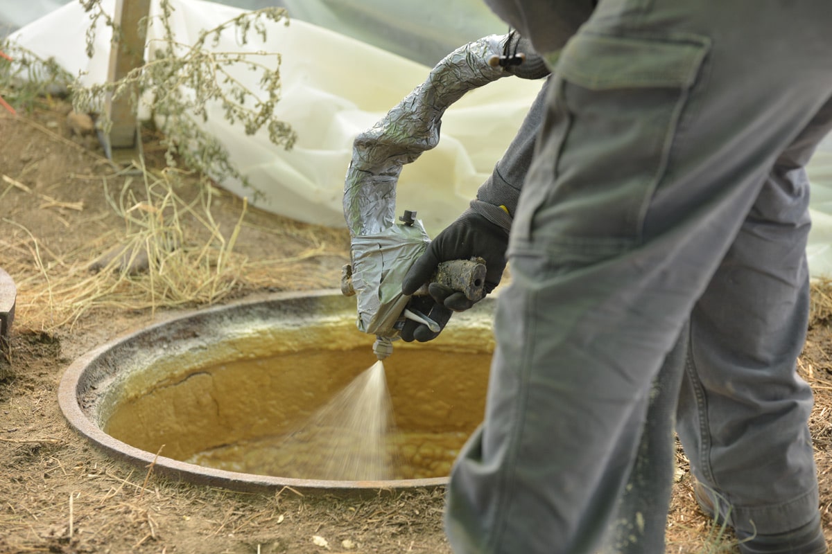
One of the contract requirements was the use of void grouting to pressurize the area outside of the CMP. This was done to fill visible voids outside the CMP. A six-port cross section from the spring line down was included within the tendered design. This cross section was installed every 8 m along the alignment. These ports were pressurized to 10 psi, where possible, and included a backflow preventer to hold the grout in place once the hose was disconnected. Challenges were experienced due the condition of the CMP. The walls of the storm sewer were severely degraded and would not hold pressure. The grout would escape through the holes in the CMP back into the trunk beside the ports.
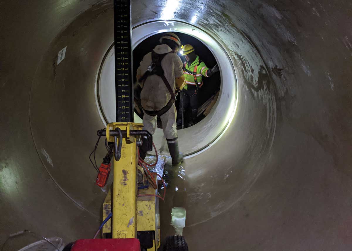
Based on the depth and composition of the storm trunk, hand placement of FRP was selected for the curved sections and jacking using a sliplining machine for the straight sections. Shaft locations were selected based on where it was most efficient to take advantage of the straight segments and where could be gained for the curved sections. Liner plate shafts were used for hand placement sliplining. Slide rail and soldier pile shafts were used to jack the pipe in with the sliplining machine. Straight sliplining sections were completed in lengths of 260 m, 440 m and 500 m. Curved sections were completed along the shorted sections noted earlier.
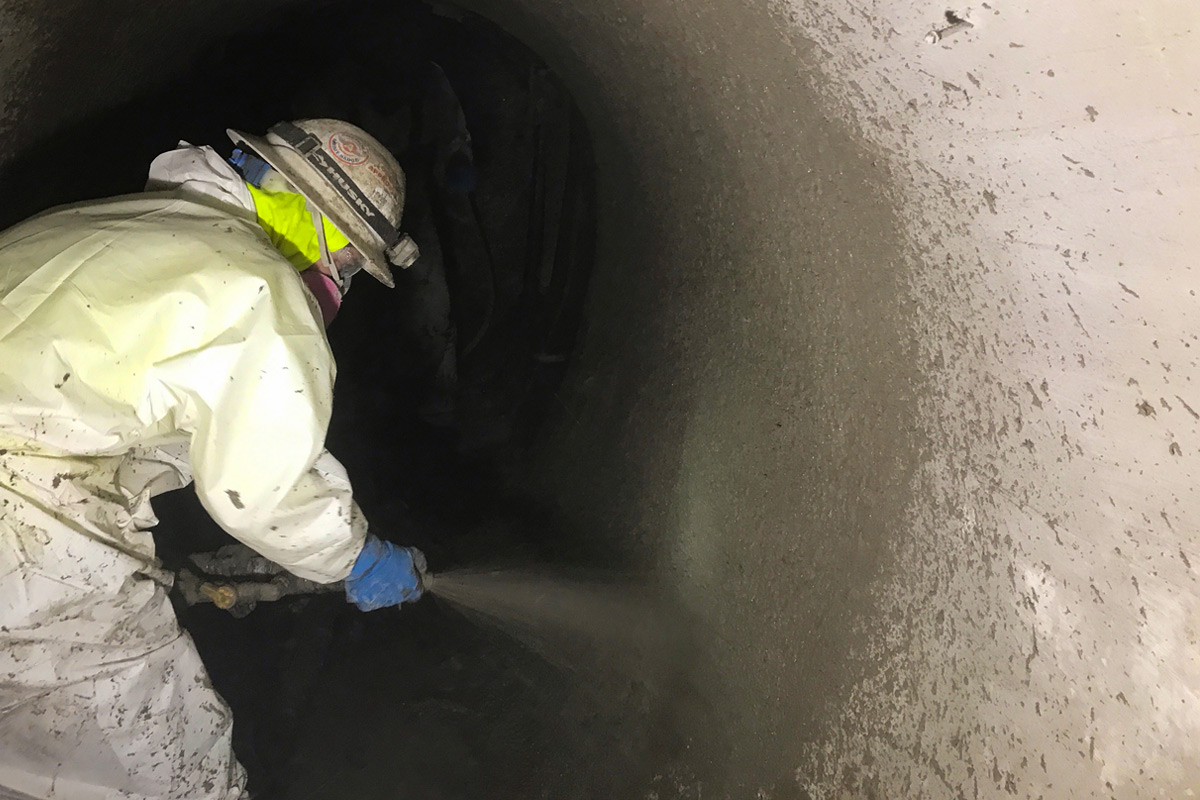
After each section was installed, annular space grouting began. The specifications called for a 6 MPa grout to fill the annular space. As the hand placed sections were blocked in place, they were grouting in one pour. Long straight sections required more consideration. The decision was made to complete the annular space grouting in long sections with shallow grout lifts as floatation was not permitted.
Various grout options were investigated including cellular grout to limit the risk of floatation. A specialized grout design was developed by the supplier using fluidity additives to have the grout flow up to 500 m. This proved ineffective at which point the long stretches were broken down from manhole to manhole. Grout ports were drilled inside the FRP pipe and bulkheads where possible to allow grouting in smaller sections. Once gravity grouting was completed, hammer testing and observation drills were used to confirm the grouting was successful. In some cases, pressure grouting was needed to fill voids in the annular space.
Sewer Rehabilitation Part B
Part B included the rehabilitation of 2,200 m of 2,337 mm diameter CMP, six manholes and two chambers. It also included the replacement of seven drill drop manholes.
Part B of the sewer rehabilitation project began with an inspection where measurements were taken noting the internal diameter every 50 m. Several offsets were found, one location of significant ovality and multiple locations of invert loss. Many manholes in this section are what are called drill drops. These are manhole structures built to the lowest lead or lateral invert to a manhole. Once in the manhole, flows enter a vertically drilled pipe in the manhole base which drops into the storm sewer. Many of the drill drop pipes had begun to sink and protrude into the storm sewer. Sections of the CMP beneath the drill drops were corroded with minimal or no invert remaining.

With the information collected during the inspection, the rehabilitation pipe size was confirmed to be 1,837 mm. The inspection did confirm that some changes were required in the proposed construction execution. Initial shaft locations were selected based on the need to remove and replace the existing drill drops. Shafts were selected to be 3.5-m diameter liner plates to fit within the standard roadway lane. Additional shafts were added at the locations of ovality and major offsets. Shaft 5 was not installed to reduce the traffic impact as it was in one of the narrowest roadways on the project. Its removal was a risk as it resulted in the longest stretch without access being 850 m.
Using the information collected during the inspection and the alignment drawings, a 3D model was created like that of the Part A sewer rehabilitation. With the 3.5-m diameter shafts, the longest pipe segments possible to fit in the shaft were assessed to be 1,500 mm in length and 1,500 mm, 900-mm and 300-mm, lengths were used with 6-, 14- and 20-degree bends with the shortest sleeve lengths possible to make it through the storm trunk. Once construction began, the maximum pipe length was increased to 2,000 mm.
Due to the challenges experienced with the void grouting in Part A, SCG suggested changes to the design to EPCOR and their consultant. The contractor and design team developed a method where the pipe would be hand placed along a section of the alignment and blocked.
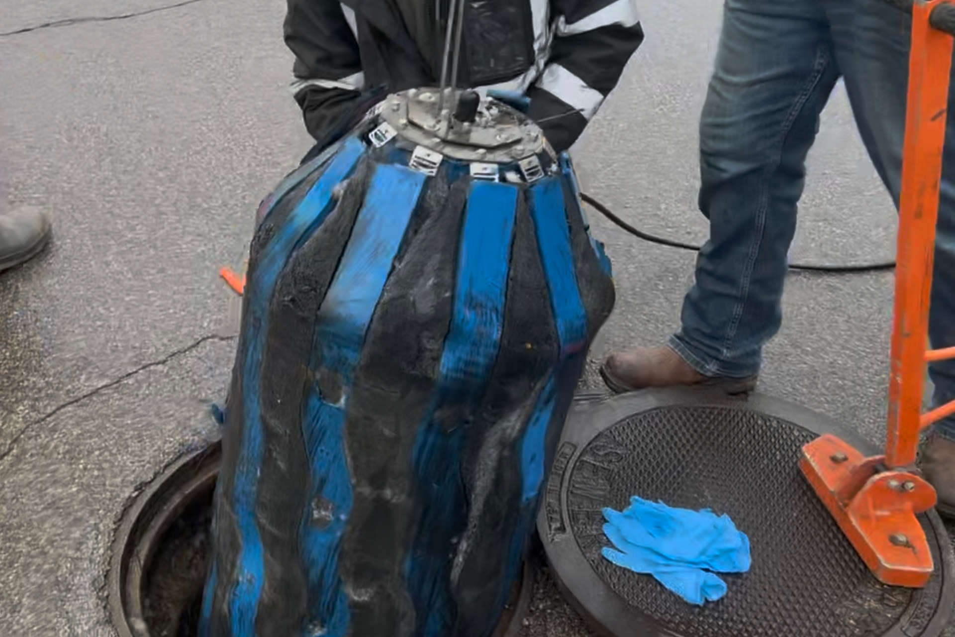
Once blocked, the contractor would install bulkheads at no greater than 100 m spacing. With the bulkheads built, ports would be drilled into the FRP placed at strategic locations to drain the water within the annular space and to pump the grout in. During the grout injection, additional ports would act as vents to let the air and the remaining water out prior to pressurization. With the air and water out, the section would then be pressurized to required 10 psi. This method was approved for use of Part B.
Required grout volumes for each section were calculated using the annular space, pipe support blocking, as well as an allowance for what was expected to be the potential voids surrounding the outside of the CMP. Based on the annular space grouting alone the estimated grout volume needed for Part B was over 2,200 m3.

Void volumes for the pressure grouting from Part A were calculated to be around 20 per cent over that of the annular space. Within the first three sections an average of 27 percent of additional grout was used. This equates to an average of just over 11 m3 of extra grout per section to fill voids surrounding the CMP. The team considered this a success and continued with the design and procedure for the remainder of the project. Quick setting concrete mortar was used for the bulkheads. Sliplining and grouting of the 2,200 m alignment was broken down into over 60 sections to manage the needed grout volumes. While there were three or four bulkheads which did not hold pressure over the course of the project, the method was effective in its application.
Large grout volumes were needed to fill the annular space between the outside of the 1,837-mm FRP and the inside of the 2,337-mm CMP. Completing each section prior to the grout beginning to set was critical to utilizing pressure to fill the voids outside of the CMP. While the grout supplier was able to provide the needed volumes, it was the ability to pump the grout volumes down the long stretches into the annular space which was the pinch point. In total a grout volume of 2,638 m3 was used with roughly 424 m3 of it being used to grout voids outside of the CMP.
Overall, the project was successful in not only the rehabilitation of the existing line but also in the filling of voids that were created by the partial failure of the existing system. On Part B more than 2,600 m3 of grout was used to fill voids and the annular space. An estimated volume of that grout was used to fill an estimated 420 m3 of voids outside of the CMP during the pressure grouting process on Part B alone.
Editor’s Note: The Groat Road Storm Trunk Sewer Rehabilitation Phase 2 project was the No-Dig North 2022 Canadian Project of the Year Honourable Mention. The project team formally received the award at the 2022 No-Dig North Show in Toronto. This story originally appeared in the Winter 2022 edition of Trenchless Technology Canada.
Christopher Lamont, C.E.T., P.Eng., is an infrastructure engineer at Associated Engineering