Thickwood Trunk Sewer – Direct Pipe Installation
Project an Integral Component of Increasing the Resiliency of Storm, Sanitary Systems in Fort McMurray
The Regional Municipality of Wood Buffalo (RMWB) has experienced several environmental events that have caused significant damage to the region over the last decade. Floods, fires, and rainfall events have had a significant impact on the landscape and infrastructure in the region.
The Thickwood neighborhood sits near the center of the urban service area of Fort McMurray just north of the Athabasca River Valley and was developed between 1970-1985 during a time of major oilsands development.
In July 2016, 80 mm of rain fell in a short period of time which resulted in surface and underground infrastructure being overwhelmed. Manholes failed, basement flooded, and roads were damaged in a number of areas in Fort McMurray including Thickwood. The standards the neighborhood was designed were dated. They did not take into account the impact associated with inflow and infiltration and they did not utilize overland storage locations during major rainfall events to attenuate times of peak flow.
Prior to the major rainfall, the RMWB had been working on and had nearly completed updates to the wastewater, stormwater, and water master plans. These updated master plans identified opportunities to combine infrastructure improvements needed in water, sewer, and storm systems across Fort McMurray with major improvements specifically within the Thickwood area.
Working with the RMWB, Associated Engineering was retained to design major upgrades for the water, sewer, and storm across the Thickwood Neighborhood based on the various master plans.
Due to the size and density of the neighborhood, the use of green spaces to store peak flows during a storm event was not considered a viable option.
The second option was the construction of a new storm trunk system and outfall to the Athabasca River. The upgrading of the stormwater system was paired with the improvements of the water and sanitary sewer systems on all roadways where the storm trunk would be installed.
Due to the size and scope of the upgrade program, the work was broken down in several stages. The first being the new outfall into the Athabasca River and the major trunk traversing the river valley and its slopes.
Preliminary Trenchless Design
Route selection for the first phase of the new storm sewer was made based on the general topography of the area. Fort McMurray is set within the boreal forests at the convergence of the Athabasca and Clearwater Rivers in a river valley with slopes as high as 80 to 100 m.
In an effort to minimize tree clearing and the removal of naturalized area, the alignment was set down a utility right of way parallel to existing large diameter watermains and telecommunications cables. This alignment was within one of the more gradually sloped areas and includes a ridge with a drop of roughly 30 meters before entering the lower river flood plain at the river’s edge.
While the lesser more gradual slopes could be done by open cut, the geotechnical investigation identified the ridge as being unstable, prone to slope failures, and stated that open cut was not suitable for that area of the storm trunk. Other challenges existed at the bottom of the slope. An oil and gas pipeline corridor containing several high-pressure lines, a sewer forcemain, and large diameter watermains all needed to be crossed and the primary access road to the Fort McMurray water treatment plant needed to remain open. Directly adjacent to the pipelines and roadway was an old impound lot which was considered a contaminated area under remediation; no excavation was allowed.
RELATED: Associated Engineering: A Proven Trenchless Track Record
Proper sizing of the storm sewer outfall requires knowing the grade of the installation to complete the needed modelling. Preliminary modelling estimated the size to be a 1,800-mm diameter, depending of the grade of the installation. Installation method then became an important consideration.
A number of trenchless methods were considered for traversing the 30-m elevation change beneath the slope failure zones with the primary method being microtunnelling.
Preliminary designs were developed followed by a geotechnical investigation. In addition to the slope failure, the geotechnical report outlined a complex stratigraphy of clay, clay till, dense seams of sands and gravels, cobbles, boulders, oilsand deposits, clayshale, and limestone. Encountering all these conditions in one installation would prove challenging for any trenchless method.

Selecting the Right Trenchless Method
The microtunnelling design options required the use of a large deep drop shaft which was a major concern for the client due to the challenges associated with access and maintenance. This option was removed from consideration by the RMWB.
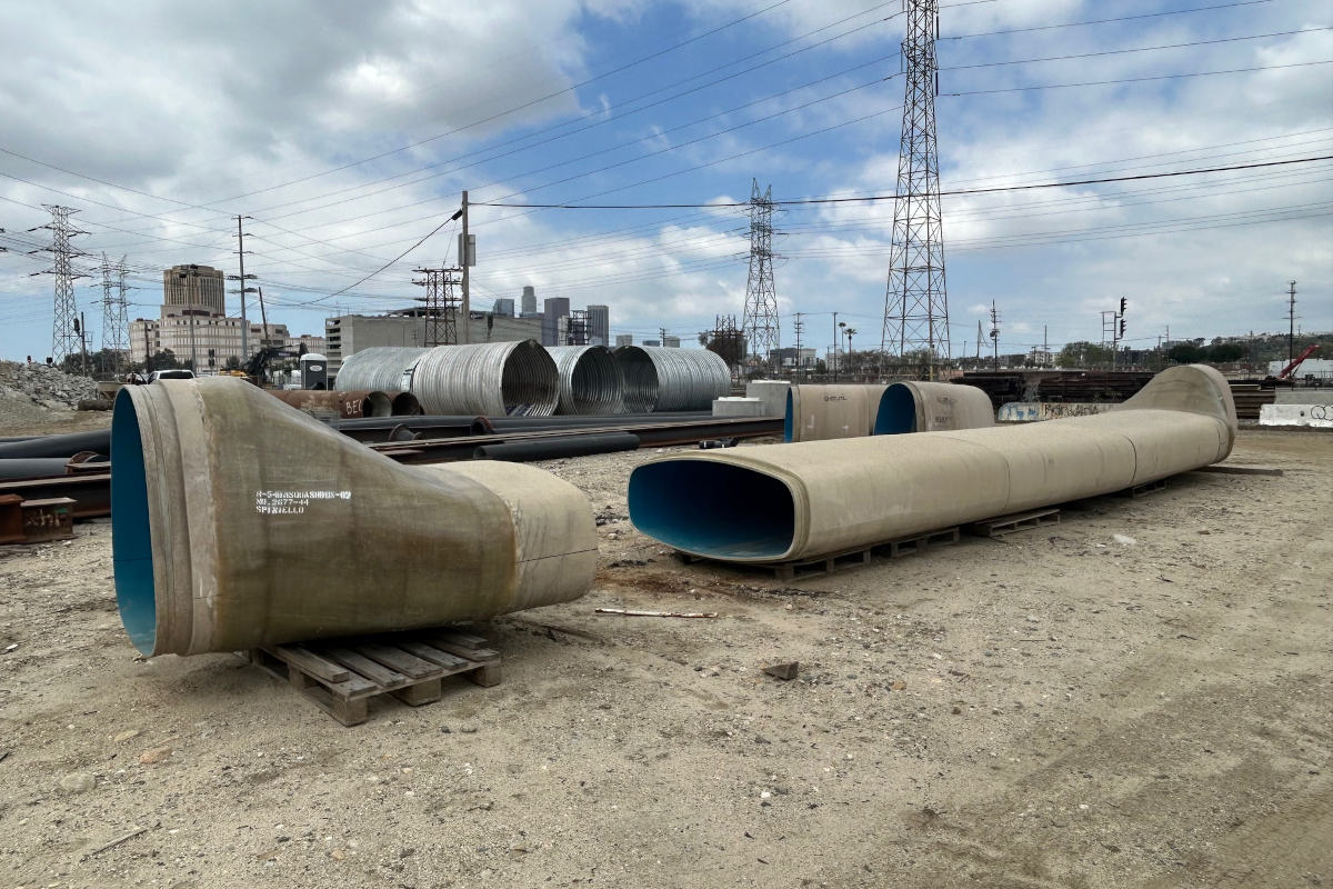
In searching for other viable options, two trenchless methods were further considered, horizontal directional drilling (HDD) and Direct Pipe. Preliminary borepaths were developed for both options to confirm the needed size by hydraulic modelling. Both methods allowed the slope of the installation to be increased significantly which increased flow and allowed for a decrease of needed pipe size from the original 1800mm diameter.
Subsequent modelling found that a 1,200 to 1,500-mm diameter pipe would be suitable for the anticipated flows based on the expected grade. Both Direct Pipe and HDD required the use of steel pipe. The allowable bending stresses and steering requirements of such a large pipe would require consideration as the alignment included a compound curve, a simultaneous horizontal and vertical bend. Achieving the steering and maintaining a bend radius suitable to not over stress the pipe and stay in the utility right of way was considered to be one of the major concerns, especially knowing the geotechnical conditions.
RELATED: Direct Pipe Is No Panacea, but it Could be the Right Solution
The borepaths developed for both methodologies, which were significantly longer than the microtunnel option originally considered. As a result of the site constraints, the project scope grew as the watermains control chambers now fell within the project workspace.
The two options were refined further, and final hydraulic modelling done which confirmed the 1,200-mm diameter. While this diameter is within the feasibility for Direct Pipe, it was on the higher end of the feasibility for HDD.
Considering the challenges expected with both methods of construction, the decision was made to prequalify the trenchless contractors. Since there were a limited number of Direct Pipe contractors, the decision was made to qualify both methods to bring the project forward to more contractors who might be interested. Prequalification was completed during the detailed design stage. As a result, one HDD and two Direct Pipe contractors qualified.
Between the time of prequalification and tender, the project team decided that the HDD option was too high risk because of the size and the potential collapse of the large layers of sands and gravels. Direct Pipe was selected for the tender and construction of the storm sewer.
With the final stress calculations completed and profile developed, the final design was just under 470 m in length with an elevation difference of 33 m between the inlet and outlet section of the steel storm trunk. Crossing restrictions identified by various utility owners. primarily beneath the oil and gas pipelines, revealed a 50-mm elevation tolerance. This was due to the separation required from beneath the pipelines and the elevation needed to grade to the river.
Direct Pipe Construction
The project was tendered giving the general contractors the option to solicit pricing from the two noted prequalified trenchless contractors. Project tender and award occurred in early 2019 with the project being awarded to Sureway Construction with their trenchless contractor Innovative Pipeline Crossings (IPC) – now Bothar.
RELATED: Essential Upgrade: Slave Lake Raw Water Intake Part of Wildfire Recovery Efforts
Work on the project began with the development and review of the construction procedures and material submissions. Pipe procurement started in the spring of 2019 with construction in the fall of the same year.
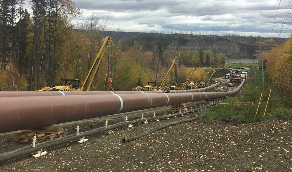
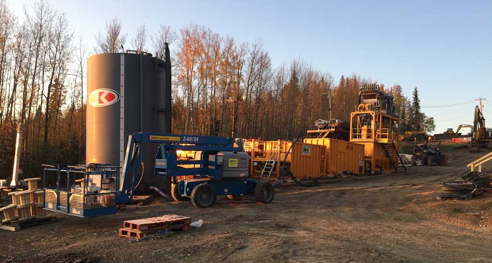
The lining and coatings were an important consideration on the project and were required to be protected during the installation. Coatings were done using a combination of mechanized and hand applied methods. With the pipe in place, setup of the systems umbilicals, separation plan, power generators, and system commissioning began. Slurry lines, power cables, communication systems, and in line pumps were installed inside the steel pipe sections by assembling them at the upstream end of each pipe segment. Due to the length of available workspace a single pipe section was not feasible and the installation was broken down into two pipe segments.
The gradual slope along the open cut section was used to stage the pipe and slurry reclaiming system. While the slope was gradual, the overall elevation difference of the slurry system increased from the original 33 m to over 80 m from the slurry plant to the reception pit based on the contractors selected location. The contractor overcame this with the use of additional inline pumps to feed and return the slurry. These pumps were placed within the 1,200-mm steel pipe at strategic locations.
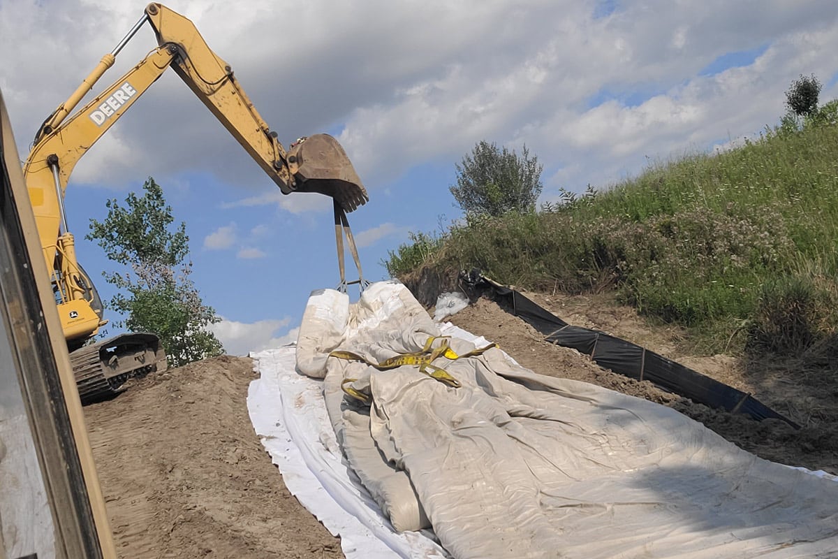
Construction of the launch pit required the use of a sheet piling retaining wall to support the existing fiber optic line on one side. After the sheet pile wall was completed, an anchoring system composed of screw piles was installed and prepared for the frame. The thruster frame along with the casing and casing seal were installed at surface.
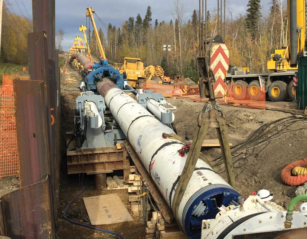
Tunnelling and thrusting operations began in early October initially mining through the clays, sands, and gravels. In the first day of tunnelling 60 m was completed and work stopped to complete the first survey control check where no issues were found. Over the course of the installation three survey stoppages were required and carried out to confirm the tunnelling was online. This was due to the critical crossings of the oil and gas pipelines. Tunnelling continued after the survey confirmation and after three days of tunnelling, 163 m had been installed.
RELATED: HDD and Pipe Ramming Used to Install Water and Wastewater Lines in Wood Buffalo
Shortly after reaching 163 m, pumps began to experience challenges with the circulation pressures due to the elevation difference. Various pump components were required to be changed out before tunnelling could continue. When tunnelling resumed the ground conditions changes to clayshale, oilsand, and limestone formations. This was anticipated and slurry composition was modified to account for the changes in ground, but production slowed due to the strength of the limestone.
At 286 m the second survey stoppage occurred to confirm the alignment and grade into the compound curve segment. Upon restarting the pumps, challenges were experienced with the pressure again. This required the replacement of a slurry pump on the umbilical system in the steel pipe. Replacement of the pump required disconnection, removal, and replacement of all the umbilicals upstream of the pump. Once the pump was replaced, tunnelling continued to around 300 m where the mid-drive weld connecting the two pipe segments and coatings were completed.
Once through the limestone and the final tangent, the cutter head reached the reception pit and the elevations were surveyed again. This confirmed the final elevation to be 41mm lower than the design invert and within the specified tolerance. A review of the complete as-built data showed that the alignment was kept to required tolerances along the entire alignment.
Christopher Lamont, C.E.T., P.Eng., is an infrastructure engineer at Associated Engineering. Mason Ross, P.Eng., is a project manager for the Regional Municipality of Wood Buffalo. Jason Lueke, Ph.D., P.Eng., is the national practice leader for trenchless technologies at Associated Engineering.