Murray River Crossing in Northeastern B.C. – HDD for 48-in. Pipe
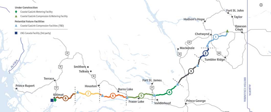
Northern British Columbia represents some of the most challenging pipeline construction conditions in the world, all of which the 670 km NPS 48 (48-in. diameter) Coastal GasLink Pipeline must traverse to reach the LNG Canada facility in Kitimat, British Columbia. Obstacles encountered, include the Murray River, a large river with a ~140 m wide channel located east of Chetwynd, British Columbia.
Due to the identified environmental sensitivities and the challenging site characteristics, which include steep banks on either side of the river channel, a trenchless option, in this case horizontal directional drilling (HDD), was selected to construct the crossing.
Geotechnical Investigation
Along the proposed alignment WorleyParsons Canada Services Ltd. completed a geotechnical borehole investigation and geophysical survey to inform the trenchless design. A geohazard assessment by Golder Associates Ltd. was also completed to with a particular focus on the steep eastern bank of the river.
Six geotechnical boreholes were completed to depths ranging from 60 m to 130 m in the borehole investigation. An electrical resistivity tomography survey was completed along the alignment on either side of the river for the geophysics investigation. The results of these two investigations found that challenging conditions were present for any type of trenchless installation.
These conditions included shallow bedrock beneath the river channel itself, however deep deposits of gravel were present overlying the bedrock on either side of the river. The bedrock was found to primarily be layers of sandstone, siltstone and shale.
RELATED: Addressing Steering Challenges on HDD Crossing in Canada
The geohazard assessment indicated that there were some landslide risks along the valley wall of the Murray River, further east of the potential workspace for trenchless crossing. The hazards associated with the landslides were assessed to be far enough away that it would not impact any of the potential trenchless installations.

A Durango tool was used to excavate ahead of the casing to allow the installation to continue.
Trenchless Method Selection
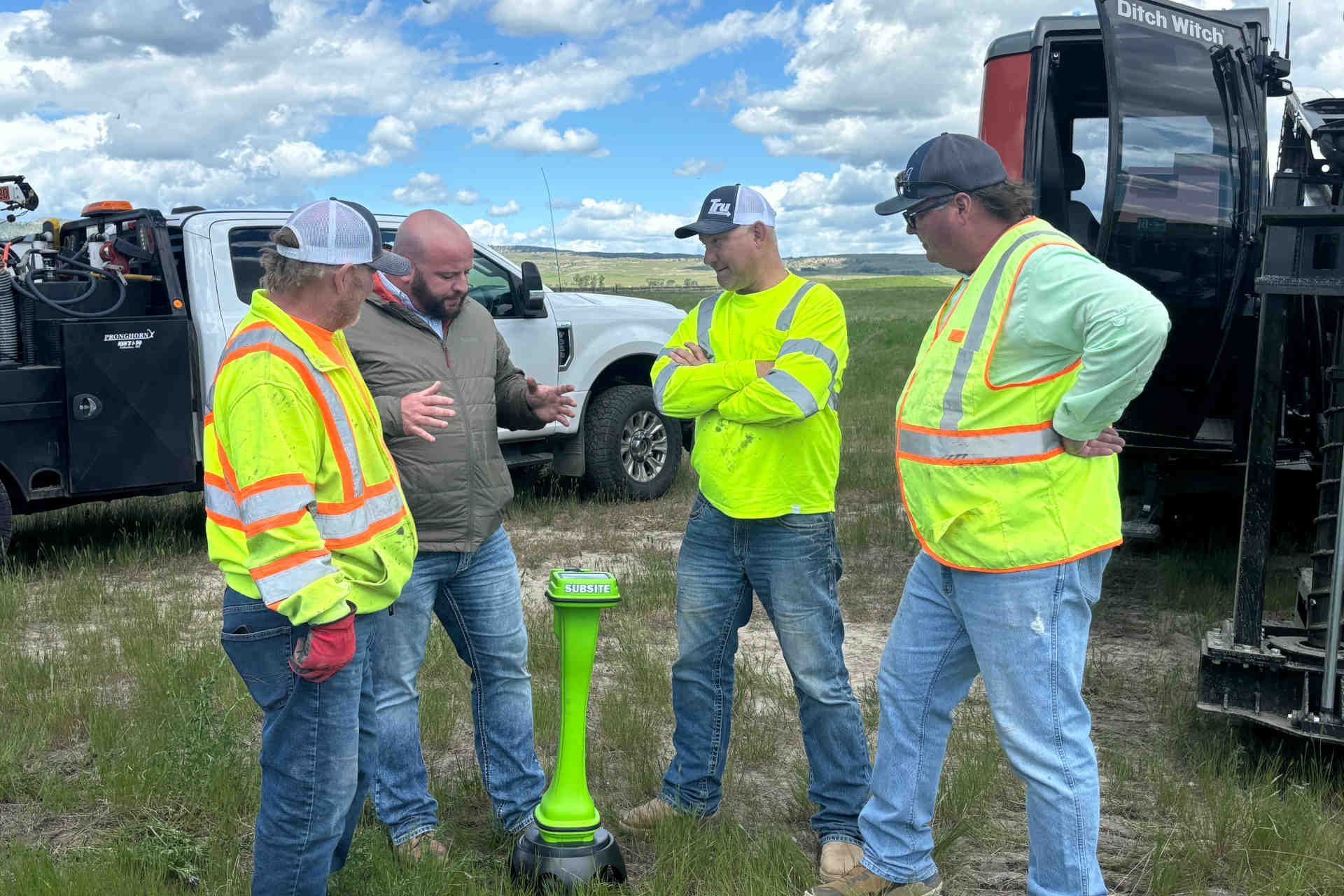
CCI Inc. was engaged by Coastal GasLink (CGL) to complete the trenchless engineering on the crossing and reviewed the available data.
After multiple reviews of all trenchless crossing options, the original proposal of a highly challenging HDD remained the best choice. The steep banks, geotechnical conditions, pipe specifications and environmental considerations, made other options such as auger bores and direct pipe thruster microtunnelling (commonly Direct Pipe). The auger bore (or other straight bore options) were complicated by the large excavations required, the shallow bedrock, and the length of the installation required. Direct pipe thruster microtunnelling was a less desirable option as the length of crossing required due to the large bending radius extended the installation to lengths well beyond previously completed installations. Additional challenges included the high elevation change across the crossing profile and combination of overburden and bedrock tunnelling added significant complexity to the execution of the tunnel.
The original HDD considered in the development of the pipeline alignment was almost 1,600 m in length. One primary reason for this was to mitigate the risk of fluid release to the river during drilling activities. The other major risk associated with the HDD installation was the requirement to install temporary surface casing to support the borehole through the overburden soils, where gravel and cobbles could collapse into the borehole.
With a review of the geotechnical and geophysical installations, CCI was able to model the restraining pressure of the bedrock and overburden soils to justify a reduced depth of cover beneath the river channel. With the reduced depth of cover, the crossing length was able to be reduced overall and gave the added benefit of increased flexibility in the selection of the entry and exit locations of the HDD, thereby the location of the required temporary surface casing.
The casing had to be sized to accommodate the reamers required to open the borehole to the required size. For the 48-in. diameter pipe, standard industry best practices call for a final borehole size of 60-in. in diameter, therefore a 60-in. diameter reamer was required. To accommodate a reamer of this size, a minimum casing diameter of 72 in. was specified. The overall casing lengths required remained relatively high compared to common industry installations, specifically the entry casing on the east side of the crossing. CCI identified this as the highest risk for the HDD installation and it was recommended that an additional geotechnical investigation be completed to drill a borehole to determine the depth of bedrock at the potential end of the casing installation. This additional borehole was completed by Golder at the 90 per cent design stage and revealed that the bedrock at the proposed location was deeper that expected based on the previously drill boreholes and geophysics model.
Some design modifications were required to a accommodate the additional length of casing required, including extending the length of the crossing and resulted in a final HDD length of 1,347 m. Final temporary casing lengths required by the design were 58 m on the exit (west) side of the river and 114 m on the entry (east) side of the river. Other design elements incorporated to optimize the casing requirements included the selection of a 21-degree entry angle. While this entry angle was steeper than the industry standard maximum of 18 degrees, the payoff of the shorter casing was considered worth the expected challenges with modifying equipment to set up at the required angle and the expected difficulties with transporting soil and bedrock cuttings out of the hole at the steeper angle.

The maximum pull force measured during the pull was 886,000 lbs. This graph shows a record of the pull forces throughout the pullback. The four highest spikes seen in the record of maximum pull forces (circled in red) are the instances where the hammer was used.
All risks associated with installation of the casing were heavily reviewed. The primary risk was that the casing would not be able to be installed to competent bedrock material, leaving a portion of the borehole unsupported, increasing the risk of borehole collapse, as well as the risk of drilling fluid being released to surface in that area.
A secondary risk that was heavily considered was the accuracy of the casing installation. With tight steering tolerances and minimal tangent available to make corrections, specifically on the east side of the river, the casing installation would have to be installed accurately to allow the remaining HDD to be completed within the required specifications. This proved to be the risk that materialized during construction.
Careful consideration was given to potential mitigations to install the casing accurately to the required depth. Discussions included telescoping the casing and a variety of installation equipment, even installing the casing with a retractable microtunnel boring machine. Ultimately, relatively standard practices were used to install the casing including a 90-kilojoule hydraulic hammer and telescope method. Telescope methodology is where the installation near surface begins with a much larger casing diameter, in this case 96 in., then progressing to an intermediate size of 84-in. diameter, before reaching the final minimum diameter of 72 inches at the final depth. This method reduces the overall friction required to be overcome in the installation.
Intersect drill methodology was specified due to the required casing installations. This also helped reduce the risk of drilling fluid being released to the surface.
RELATED: From Beginning to End – CCI Inc. Fills Niche in Trenchless Crossing Consulting
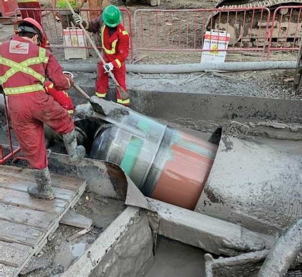
Construction
Construction of the Murray River HDD began in autumn of 2020 with entry casing installation by Surerus Murphy Joint Venture (SMJV) and The Crossing Company (TCC).
For the extensive entry casing installation required, reviews of the material at the final depth of the casing and the survey of the casing alignment were required prior to progressing to the pilot hole stage. In addition to the hydraulic hammer used to complete the installation; a Durango tool was used to excavate ahead of the casing to allow the installation to continue after refusal at approximately 100 m. The Durango tool excavated outside the end of the casing to allow casing installation to continue. The casing encountered bedrock at 108 m depth, 6 m shallower than specified on the design. The exit casing installation had not been initiated to allow for the final position of the entry casing to be assessed and confirm the suitability of the entry casing installation for the designed drill path.
During installation, the 108 m of unguided casing deflected from the designed, optimized path meaning that it would be extremely difficult to maintain the pilot hole of the HDD within the designed tolerances. The design was updated to maintain the designed crossing length while providing a feasible drill path for the contractor to follow based on the surveyed location of the end of the casing.
The strict steering requirements for the pilot hole did lead to an increased schedule though TCC was able to complete the intersect within specifications based on the updated design.
Due to the steep angle of the borehole on the entry side of the crossing, there was difficulty transporting soil/rock cuttings out of the borehole, leading to additional mitigations required to improve cuttings transport. This included additional time circulating fluid within the borehole, both from the tooling currently in use as well as from an additional drill string run in to pump fluid to the end of the entry casing.
The force required to pull the large pipe through the 1,347-m long borehole were expected to be high and could be heavily influenced by downhole conditions. Limits of the drill pipe were evaluated and a contingency plan of using a 24-in. pneumatic hammer on the back end of the product pipe to assist with the pullback. A 5-m long pup was mounted to the back end of the product pipe prior to pullback to allow the hammer to be quickly mounted to the back end to hammer on the pipe. This contingency was implemented as the pull forces climbed above 700,000 lbs.
The use of the hammer assisted the drill rig in getting the pipe moving again to allow the pipe pull to continue, leading to the successful pullback of the 1,347-m long NPS 48 pipe.
With collaboration from all participants, and careful considerations of potential risks, one of the longest NPS 48 pipe HDD’s in North America was completed through challenging conditions.
Thomas Husch, P.Tech.(Eng.) is a project coordinator for CCI Inc.