Microtunneling for the N. Clarksville Water Treatment Plant
Clarksville, Tennessee’s industrial growth has been explosive during the past five years, and the associated potable water demands were projected to eclipse the existing facility’s capacity in under five years. As such, Clarksville Gas & Water needed to build a new water treatment plant to supplement its existing facility.
The City of Clarksville procured a new north Clarksville water plant site on the Cumberland River off Barge Point Road. The new water plant is the single-largest capital expenditure in the City’s history and is expected to be in production to deliver safe and reliable drinking water by mid-2025.
The new plant intake is located downstream of the confluence of the Cumberland and Red rivers. Construction is being performed in three phases, with each phase having the capacity to generate 12 million gallons of water per day, for a total of 36 million gallons at final, full capacity.

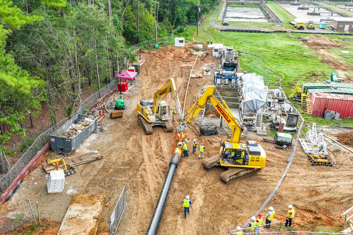
The raw water intake scope includes constructing an approximately 80-ft wide by 50-ft long drilled and blast jacking shaft with a depth of 80 ft, which, after tunnel construction, will be used as a pump station. It also includes the construction of approximately 470 LF of 87.5-in. Permalok Steel Casing via microtunneling, with an underwater retrieval of the microtunnel boring machine (MTBM) from the Cumberland River utilizing barges and the installation of one 48-in. ductile iron pipe (DIP) raw water intake carrier pipe, one 10-in. CA-DIP air pipe, two 1.5-in. OX-SST chemical lines – all installed with casing spacers.
Additional work included the installation of blind flanges and bulkheads, placement of cellular internal annular backfill, riverbed slope correction with the placement of a tremie concrete block underwater, installation of carrier pipe on top of the micropiles between the end of the casing and fish screens and installation of isolation kits and intake fish screens.
In August 2021, Judy Construction Co. was the low bidder on the project and selected Smith Contractors, specializing in water and sewer lines, water and wastewater treatment plants, marine construction, blasting, etc., to perform the raw water intake, pump station, raw water transmission and storage scope of work.
Smith Contractors later selected Huxted Trenchless to perform the microtunneling portion of the work based on the company’s extensive experience with wet microtunnel machine retrievals. Huxted has successfully executed multiple and similar underwater retrieval projects in many states, using internal flanged bulkheads.
The subsurface conditions along the project alignment generally consist of a full-face limestone stratum with a UCS ranging from 76.7 MPa to 147.4 MPa, indirect tensile strength ranging from 5.3 MPa to 8.6 MPa, Cerchar Abrasivity Index ranging from 1.1 to 1.5 and RQD/REC both at 98 percent, per the available geotechnical report.

Only one set of bore logs was provided in the geotechnical report located at the tunnel’s retrieval end.
Groundwater in the borings was initially encountered at 28 ft below grade and 46 ft above the tunnel flowline. When confronted, the groundwater could be pressurized. For reference, the Cumberland River’s 100-year flood elevation is 390.00, the record flood elevation is 393.43, the normal pool elevation is 359.00, the minimum water elevation is 355.00, and the raw water intake pipe flowline elevation is 333.00. The microtunnel was installed with a water head over 40 ft, and the invert was approximately 74 ft deep.
Smith Contractors installed an approximately 80-ft by 50-ftdrilled and blast jacking shaft. Shaft construction started in May 2022, and Huxted fully mobilized in early March 2023.
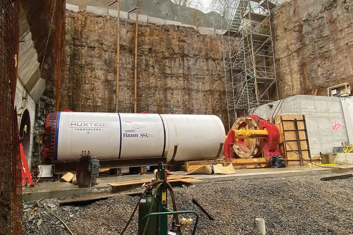
Based on the subsurface conditions, Huxted elected to use a Herrenknecht AVN 1800 MTBM with face access for cutter changes, a 150 MPa rock cutting wheel specifically designed for this project by Tunnel Service Group and a sacrificial trailing can with an exterior cut line was designed in-house with dual bulkheads to keep the MTBM and tunnel dry during the underwater retrieval.
The chosen MTBM, with its face access for cutter changes, was perfectly sized for an 87.5-in. Permalok Steel Casing with a 1-in. wall thickness; jacking forces never exceeded 200 tons. A conventional laser active targeting system ensured the tunnel line and grade were completed well within the specified tolerances.
Huxted elected to use a double-flanged entrance ring with a dual seal and a pipe brake. Huxted’s tunneling production averaged 20 lf per shift, and before the microtunnel machine reached the river, Smith Contractors constructed an underwater rock exit face, an approximately 15-ft long landing pad. The landing pad was built approximately 6 inches below the tunnel invert and backfilled with crushed rock. After excavating through the rock exit face, with the assistance of divers, Huxted pushed the MTBM onto the landing pad and exposed the sacrificial trailing can with the exterior cut line.
After launching the MTBM and tunneling approximately 26 ft, the tunnel crew observed a leak in the MTBM steering joint. Per the manufacturer’s recommendations, the crew adjusted all the seal compression bolts on the steering joint to stop the leak. unfortunately, the leak did not stop.
Given the risk associated with the underwater retrieval and further discussions and investigations, it was determined that the steering seal needed to be replaced to mitigate the leak. Thus, the MTBM must be pulled back into the launch shaft to replace the steering seal.
The MTBM was pulled back, and while the seal was being replaced, the crew noticed excessive wear on the cutters after only mining 26 ft. After examining the geotechnical formation at the face of the tunnel and comparing it to the project geotechnical report, some irregular rock formations indicated a higher-strength rock. A local rock coring company was hired to take four samples at the tunnel face.
The samples were shipped to the Colorado School of Mines for testing. The testing results showed that the Uniaxial Compressive Strength of the rock samples was 222.0 MPa, which is a 50.61 percent increase in rock strength from GDR, and the indirect tensile strength was tested at 10.2 MPa, which is an 18.60 percent increase in tensile strength specified in GDR. The Huxted team immediately notified the EOR and provided all the testing data and analysis.

The 150 MPa cutters were designed to be more abrasive-resistant but not designed to handle harder rock. Thus, the discs were damaged much faster than anticipated. For this project, a maximum rock strength of 147.4 MPa was expected, as noted in the geotechnical report, with most tests measuring below 87 MPa; however, a higher rock strength of 222.0 MPa was encountered.
Thankfully, Huxted’s team pulled back the MTBM and noticed the wear on the original cutters, or significantly more cutter changes would have occurred. The manufacturer of the cutting head was contacted, and multiple sets of 250 MPa full-hardened steel disc cutters were procured.
After replacing the 150 MPa cutters with 250 MPa full hardened steel cutters and the damaged steering seal, the MTBM was relaunched, and tunneling continued.
At 233 ft, the gauge and some face cutters were replaced, and at 387 ft, the complete set of cutters ware replaced. However, most discs did not need to be replaced, but due to the potential of less desirable rock conditions that would have made face access more complex, it was decided to replace all the discs.
When the MTBM reached the recovery location, Huxted’s crew removed all tunnel utilities, and the two watertight bulkheads were closed on the sacrificial trailing can, one to seal the MTBM and the other to seal the tunnel. The tunneling equipment was also removed from the shaft bottom, and the sacrificial trailing can between the MTBM and Permalok casing was filled with water — equalizing water head pressure between the adapter, thus allowing an underwater cut to remove the machine.
After balancing the head pressure, the divers cut the pipe adapter off and the MTBM was removed. The divers’ team supported the MTBM with airbags while cutting the MTBM from the pipe and throughout the retrieval process. After retrieving the MTBM, Huxted’s crew pumped contact grout to fill the exterior annular space between the casing pipe and the rock. The carrier pipe bundles mounted on casing spacers were installed into the tunnel from the launch shaft. Once the carrier pipes were installed, the internal annular space was grouted with cellular grout.
Many lessons were learned from the project:
1) The owner/engineer must obtain more geotechnical information and collect multiple samples for testing; 1 boring for this diameter and length of tunnel is not recommended.
2) The contractor should have collected more samples during shaft construction for testing.
3) The contractor should have cored the face of the launch shaft wall as soon as the shaft excavation is completed and perform more testing.
4) Submit requests to the owner/engineer for additional subsurface exploration along the tunnel alignment during the prebid phase; one set of bore logs was provided in the geotechnical report, located at the tunnel’s retrieval end.
5) A GBR is suggested to help mitigate potential claims on rock tunnels.
Harsha Reddy is senior project manager at Huxted Trenchless and Cheryl Levin is marketing manager at JAG Companies.