King County, Wash., Takes on Challenging Project to Control CSOs
September 2, 2015
Horizontal directional drilling (HDD) projects continue to progress into more and more challenging applications. ‘At-grade’ HDD techniques or drills where the profile is maintained at a constant grade to allow for gravity flow applications are a particularly challenging application — especially as pipe sizes get larger and alignment lengths get longer.
To further add to the complexity of the project, a series of three horizontal curves were also necessary to connect the entry and exit locations and remain primarily within the available public right of way.
One recent example of HDD technology and a strong project team overcoming a unique set of technical challenges, including an ‘at-grade’ application, occurred in Seattle. A 32-in. outer diameter (OD) gravity sewer pipeline was installed using HDD methods for King County to reduce combined sewer overflows (CSO) into Elliott Bay. This large design-bid-build project included a 3,151-ft HDD that required a grade of 1.8 percent through a glacial bluff to convey flows into a 1.5 million-gal retention storage tank.
The new pipeline augments an older section of King County’s wastewater system, which was comprised of a single pipeline to carry both sewage and stormwater runoff. This combined sewer collection is routed to a wastewater treatment plant that treats the waste stream; however, during periods of heavy rainfall, the pipeline can easily surcharge, leading to a CSO into Puget Sound.
King County implemented this project to meet the requirements of the Washington State Standard and to reduce the frequency of CSOs into Puget Sound, which can pose a risk to public health and the environment. Currently King County has reduced CSOs by 90 percent countywide, and succeeded in keeping more than 2.3 billion gals of sewage out of local waterways.
Design Challenge
Tetra Tech Inc. was the lead designer for the project and Staheli Trenchless Consultants provided trenchless expertise to create the design team. The design of the new pipeline was originally envisioned to carry flows from an existing diversion structure to the site of the new storage tank; however, the slope on the pipeline would have been very shallow — beyond what could reasonably be maintained with HDD technology. As a result, the design team shifted the western end of the alignment upstream and uphill to increase the elevation differential between the upper and lower sections of the bore, providing a steeper average grade. This increased the grade to 1.8 percent, forcing the construction of a new diversion structure to transfer flows into the pipeline at the higher elevation.
To further add to the complexity of the project, a series of three horizontal curves were also necessary to connect the entry and exit locations and remain primarily within the available public right of way. The three curves (55 degrees at a 1,150-ft radius, 15 degrees at a 1,150-ft radius, and 8 degrees at a 1,500-ft radius) created a challenging pilot hole alignment. Conductor casings were required at both ends of the bore, necessitating the HDD intersect method. With the horizontal curves making up more than half of the length of the crossing, there was very little opportunity for a pilot hole intersect location. The location selected to make the intersect was in the longest tangent section of the pilot hole, approximately 850 ft from the drill rig entry side.
The design team determined that gravity flow could be maintained if the pipe had a minimum slope of 1 percent and a maximum slope of 3 percent over two drill pipe joints — approximately 60 ft — with no reverse slope allowed along the alignment. These requirements were included in the technical specification for the project. The design team did have concerns regarding the history of large diameter HDD on-grade pipeline installations and its ability to meet slope requirements, as very few on-grade installations at this diameter had ever been completed. In addition, the installation traversed beneath a large bluff, resulting in depths of more than 150 ft. The design team was aware that this made accurate tracking of the bore very difficult with existing technology.
Strategic Project Set Up
The construction team, consisting of Walsh Construction as the general contractor and Mears Group Inc. as the drilling contractor, spent considerable time planning the drilling sequence. Prior to mobilizing the HDD equipment, 15-ft deep entry and exit pits were excavated to allow for construction of the bore, as well as connection to the gravity sewers upstream and downstream of the HDD section after bore completion. Both sides of the bluff that the bore alignment passed through were flanked with landslide deposits. These hillsides were classified as critical slope areas. As such, the design team had to account for protection of the landslide areas — ensuring that the construction would not negatively impact the slopes or mobilize a landslide. To mitigate this risk, 60-in. steel conductor casings were installed by auger boring on both the upstream and downstream sides of the installation. The steel casings were installed for a distance of 190 ft from the lower elevation and 60 ft from the upper elevation.
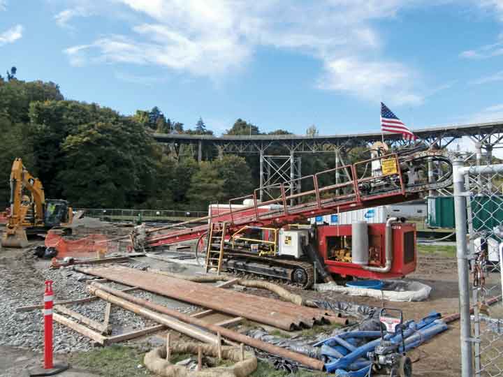
Drill rigs were also necessary at both the entry and exit side to perform the HDD intersect crossing. Mears Group set up a drilling rig approximately 200 ft back from the lower pit while its 140,000-lb drilling rig was placed directly into the pit on the upper side. The orientation of the drilling alignment had to be set up at an angle to meet the 55-ft elevation change and to maintain the required grade. When the pipe was ready to be installed during pullback, Mears employed its 440,000-lb drilling rig on the entry side.
Drilling Fluids Management

a pipe ram blow out preventer (BOP) and a rotating control device (RCD) were bolted onto a 60-in. flange at the entry side pit. These devices allow pilot hole drilling and reaming while containing drilling fluid in the hole with a mechanical seal.
The sloped profile required the use of a pressure control device to seal the lower end of the borehole so the drilling fluid would not constantly drain out due to the sloped nature of the alignment. This was the most interesting challenge of the project due to the fact that this equipment had not been used in an HDD application in this manner previously. Mears Group used a rotating control device and a pipe ram blowout preventer (BOP) to maintain a seal around the drill pipe and to control fluid and pressure while drilling the pilot hole and reaming, maintaining the pressure within an optimal range. Several ream passes were required for the drilling process to achieve a hole large enough to install the 32-in. OD Fusible PVC pipe. This required ream passes of 26, 36 and 46 in. to develop a bore with sufficient size to pull in the product pipe.
Pipe Assembly
Underground Solutions Inc. provided the Fusible PVC pipe used on the project and also provided the fusion services to assemble the pipe for the insertion. The constrained nature of the drill exit side of the project created challenges for pipe assembly and final insertion. The drill exit intersected a steep, narrow valley that included a two-lane road that ran down from the high bluffs of the Magnolia neighborhood to the bottom at Elliot Bay. The drill exit ended at an oblique angle to the road that required a horizontal bend for the pipe as it was installed in addition to the vertical ‘S’ curve required to match the alignment of the conductor casing. Additionally, in order to keep the road access open for residents along the right of way, the pipe was assembled and staged in shorter lengths, each approximately 500 to 600 ft long. These staged lengths were then assembled with intermediate fusion joints during the actual insertion of the pipeline into the bore hole as part of the final installation process. A total of five intermediate fusion joints were required, with four of them requiring a temporary stoppage of the insertion process. The roadway access was shut down for 48 hours while the installation took place.
Creative Drilling Slurry Control
Since the BOP was used at the bottom elevation on the drill rig side to keep the borehole filled with drilling slurry, evacuation of the displaced drilling slurry as the pipeline was installed posed a unique challenge. Primarily, this was accomplished by using a pull head with ports cut in it, to allow the drilling slurry to fill the pipe as it was installed, effectively ‘self-ballasting’ the pipeline during insertion. Not only did this aid with drilling slurry control, it was also advantageous in reducing the expected pullback forces to install the pipe. Additional excess drilling slurry was then removed from the drill exit pit at the upper elevation. When the pipe reached the conductor casing at the bottom of the alignment, collapsible casing spacers allowed it to be pulled into the casing, and then the drilling slurry was pumped down in front of the BOP.
Cooperation = Success
After completion of the HDD portion of the project, diversion structures and tie-ins were made at either end of the bore to create a complete conveyance for the excess combined sewer flows that occur during rain events. The success of this project was largely due to cooperation between the owner, King County Wastewater Treatment Division, the design team, the construction team, and the pipe supplier. Marty Noble, the King County construction manager said that, “Working on the project was like working with the dream team. You have the top-rated drilling contractor and the engineers to go with them.”
Kimberlie Staheli, Ph.D., P.E., is president of Staheli Trenchless Consultants. Jim Williams, P.E., is engineering manager of horizontal directional drilling at Mears Group Inc. Richard (Bo) Botteicher, P.E., is senior product engineer at Underground Solutions Inc.