Good Practices in Solids Control
October 11, 2012
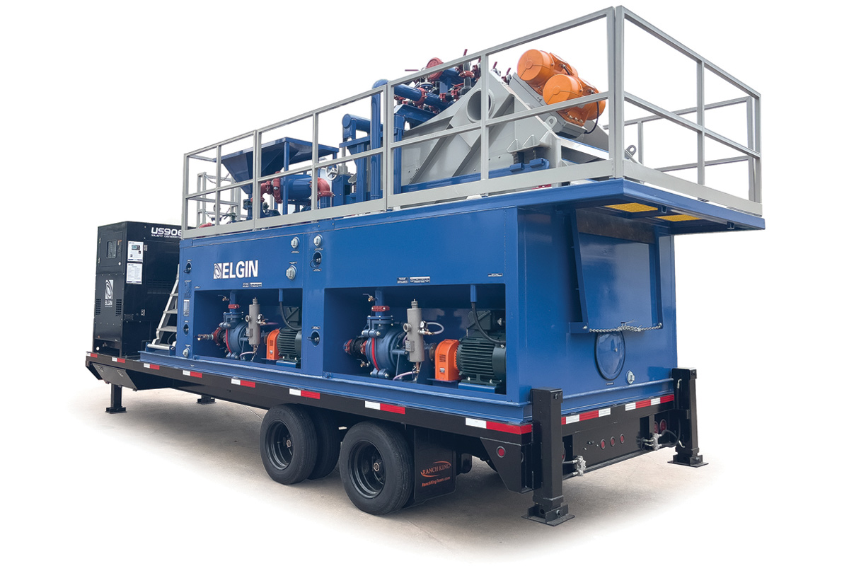
 The importance of a properly designed and supported mud recycling (separation) plant is now more vital than ever.
 The advancement of the trenchless construction industry has given rise to many more challenging and demanding projects. Drilling rigs and tunnel boring machines have evolved to meet the demands of these projects and are working in exceedingly difficult soil conditions, from high density and abrasive rock to soft, sticky clay. Furthermore, increased environmental regulations and costs for drilling mud disposal make older methods of solids control such as dump-and-dilute and gravity-settling less practical and/or uneconomic. All these variables mean it’s now an absolute necessity to have an efficient and properly sized mud recycling plant for a successful project.
Drilled solids present in the drilling fluid adversely affect rates of penetration, increase wear on downstream equipment, raise drilling mud, chemical and water usage, and can escalate disposal costs. Efficient solids control can alleviate all of these issues, which can help to lower total operating costs and increase rates of penetration (production).
Plant Design Considerations
Mud recycling plants should be designed to handle both the maximum volumetric flow and dry tonnage from the excavation process, and be capable of maintaining desired fluid properties downhole. Prior to starting the job, carefully consider the project’s specific geotechnical conditions. The most efficient plants on the market today are designed with the flexibility to handle myriad soil conditions, from coarse sand and gravel, down to colloidal solids.
 Primary solids removal is typically performed by shale shakers, or vibrating screening machines. It is critical to remove as much material as possible with the shakers, to minimize the amount of solids going into the mud tanks and being hydraulically fractured by the centrifugal pumps and slurry circuit. Shale shakers are built in various configurations, such as single and double decks, and with different types of motion. Over the years, high “G” force linear motion has proven to be the best type of shaker motion to handle almost any type of ground condition. Higher Gs breaks surface tension and reduces viscosity in shear thinning drilling fluid, which allows more fluid to pass through the screen. Faster solids conveyance uncovers more screen open area, which allows more drilling fluid to pass through the screen. This helps the shaker handle more fluid and solids, run finer screens and discharge drier cuttings. Some of the leading shakers in the marketplace today, such as the Derrick Hyperpool, are capable of producing a continuous 8 Gs of acceleration.
 Shakers are fitted with replaceable screens that are available in different size apertures, wire diameters and weaves. Until recent years, screens have been labeled by a mesh descriptor, which is defined as the number of openings per inch in both directions from the center of the wire. In the last decade, however, the oilfield has transitioned over to a new screen labeling procedure called API RP 13C, which was developed by the American Petroleum Institute (API). This change came about after repeated requests from operators for a more consistent screen labeling method that would permit better evaluation of screens based on their solids removal capabilities. The previous mesh descriptor permitted wide latitude for screen manufacturers in labeling screens. Primarily, screens were being labeled as finer than the actual cut point, in some cases quite significantly. This meant that customers were paying for a finer screen than they were actually receiving, and removing less solids.
Under the API RP 13C designation system, the screen is now labeled by an API number, rather than a mesh descriptor. The API number gives the screen’s absolute cut point, or the true d100 cut point, which means that all solids greater than that micron size will be removed. The second piece of crucial information that API RP 13C-compliant screens provide is the conductance number of the screen. The screen’s conductance, measured in kilodarcies per millimeter, specifies the screen’s ability to handle flow. When evaluating screens from various manufacturers with identical API numbers, the screen with the higher conductance number will handle more flow. Corrugated screen surfaces, such as Derrick’s patented Pyramid screen, provide increased screen area that allows for higher flow rates than older style flat screens.
Another important consideration when evaluating shakers and screens, is to consider the total “non-blanked screen area” the machine offers. This is the actual total open screen area that can be used to process fluid. The total “deck area” of the shaker is meaningless because it is not explaining how much of that “deck area” is actual non-blanked screen area for fluid to be processed.
 Fine solids and fluid that passes through the shaker screens are typically treated further by single or multiple stages of hydrocyclones. Feed slurry fed into the cone inlet at high velocity enters the feed chamber, which creates a spinning action inside the hydrocyclone similar to a tornado. Centrifugal forces and inertia cause the solids to settle outward against the hydrocyclone wall in a downward spiraling stream. Solids are concentrated and continuously discharged through the bottom of the cone, while the increasing centrifugal force near the center of the cone causes the inner layers of the downward spiraling liquid and finer solids to reverse direction and exit the overflow through the vortex finder. In many cases the recovered solids from the hydrocyclone are fed to a dewatering shaker that is outfitted with as fine a screen as possible. It is extremely important to remember to use separate compartments and centrifugal pumps for each size hydrocyclone. Each stage of hydrocyclone should be sized out to process 125 to 150 percent of the volumetric circulating and dry tonnage rate to allow them to work more efficiently and reduce the likelihood of plugging. Cleaned fluid should always be discharged downstream.
Ultra Fine Solids Removal
 The trenchless industry is seeing an increased demand for high-speed centrifuges to help remove colloidal size solids that can wreak havoc on a mud system if they are not removed. A centrifuge is a high speed, high “G” force rotating bowl and scroll assembly capable of separation down to 5 to 7 microns without chemical enhancement.
 In this process, slurry is fed through a feed tube into the rotating bowl, where centrifugal force propels the ultra-fine solids outward against the interior wall of the bowl. A rotating conveyor in the center of the bowl drives the recovered solids toward the solids discharge ports, where they are expelled into a chute. Liquid is retained in the pool and discharged through the liquid discharge ports at the opposite end of the bowl.
If desired, polymer injection or “dewatering” units can be integrated with centrifuges to remove solids down to 0um. Polymer injected in between the feed pump and inlet of the centrifuge will flocculate the reactive ultra-fine solids, forming a heavy enough mass for the centrifuge to capture. If done properly, the result can be a semi-clear effluent that may be more readily disposed of or returned to the system. This can help drastically reduce or eliminate expensive drilling mud disposal.
Ben Clark is applications manager for underground construction technologies at Derrick Equipment, Houston.


Comments are closed here.