Drill Master: Interference: The Invisible Obstacle
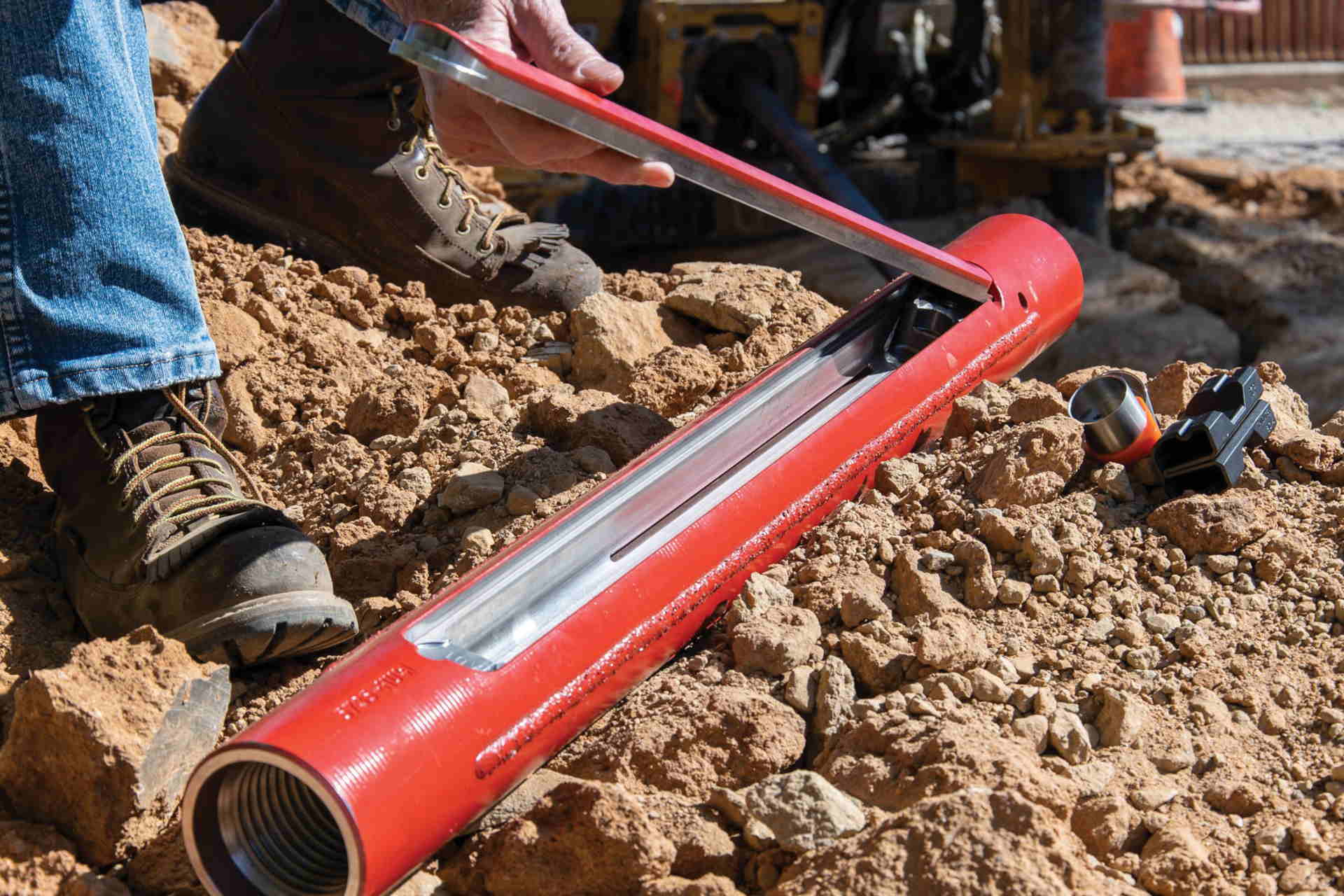
Depth, direction, pitch and roll are the most basic information displayed by all directional drilling receivers. The transmitter inside the drill head generates a magnetic field, which the receiver interprets as depth and direction. A second type of a signal broadcasts pitch, roll, transmitter temperature and battery status.
Assuming correct calibration, proper use and no outside interference, these receivers do a fine job of providing the locator with the information required to steer the head.
Since most drilling occurs in or around urban areas, interference is practically always present. Interference can be termed either active or passive. Active interference can be defined as anything that emits a signal or generates its own magnetic field. That being said, all things electrical emit a magnetic field. Examples of active interference include power lines, traffic loops, fiber trace lines, invisible dog fences and unknown sources. Do not assume that just because there is no evidence or markings on the ground that there is nothing there. Some of the possible effects of active interference on a receiver include erratic signal strength and depth readings, loss of pitch and roll data and inaccurate calibration, which may lead to depth errors.
Passive Interference
Passive interference does not generate a signal. It is anything that blocks, absorbs or distorts a magnetic field. Examples include metal structures, such as chain link fences and rebar, salt water or other unknown sources. Anything conductive has the potential to act as passive interference. Possible effects include depths appearing greater (or in some cases smaller) than they actually are, incorrect drill head location and direction, all information being blocked and incorrect calibration, which may lead to depth errors.
We need to be able to identify where interference is coming from and how one can estimate the effect on the locating equipment. This is a two-step process, the first being to walk the borepath without a transmitter turned on looking for signal readings on the receiver. The higher the signal, the greater the interference. Walk the entire path with your receiver noting the signal. Since each receiver brand displays signal in a different format, one cannot set hard and fast rules. However, the transmitter signal being read by the receiver needs to exceed the interference by a significant amount to ensure adequate signal for locating.
Once the intended drill path has been walked, it should be clear where interference is present. It should be emphasized that this first walk through tests primarily for effects on depth readings. The second part of the test involves the transmitter. The purpose is now to see how reliable the pitch and roll signal will be.
Let’s assume the planned depth for this particular bore is 10 ft (3 m). At this depth the receiver will see a pitch/roll signal from the transmitter in the ground of a given strength. Is this signal powerful enough to overcome the interference?
One way to find out is to simulate the bore in the following manner. Insert batteries in the transmitter and carry it one and a half times the anticipated drill depth removed from the receiver, which is being walked down the borepath. If the pitch and roll information is not affected during this test, it is reasonable to assume clear sailing during the bore. Although this test is quite effective, it cannot always pick up all potential problems.
Interference Options
When dealing with interference there are four main options available. The first is after identifying the interference source, see if it can be turned off. Security systems, invisible dog fences and in some cases power can be shut off temporarily. Second, is separation from the interference source. This often means locating off the actual drill path using more advanced locating methods such as off-track guidance or remote steering. This way you may effectively be out of range of the interference but still within range of your transmitter. Third, using a stronger transmitter, which in some cases may mean going to a cable transmitter, is often an effective way of overcoming the interference. Fourth, using a transmitter with a different frequency may get better results in this particular area.
The most crucial thing, however, is to fully understand how your locating equipment is supposed to function so that it becomes immediately obvious when something out of the ordinary is happening.