Drainage Drilling for CityTunnel Leipzig
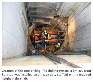 The performance of horizontal drainage drillings under a 7-m groundwater table and difficult ground conditions was a special challenge that was undertaken by the company Karo-San with a guided auger boring machine BM 400 from Bohrtec on the construction site of the CityTunnel Leipzig.
The City Tunnel of Leipzig is one of the most important inner city infrastructure projects in Germany and will connect the two railway termini stations “Leipzig Hauptbahnhof” and the “Bayerischer Bahnhof.” Due to the new rail infrastructure the trains will be able to travel underground directly beneath the city of Leipzig and will thereby achieve significant reductions of journey time. The clients for this project are the Free State of Saxony, the Deutsche Bahn AG and the city of Leipzig, represented by the “Deges, Deutsche Einheit Fernstraßenplanungs- und bau GmbH” as project controler. Contractor is the “Arge Citytunnel Leipzig” with the companies Dywidag, Alpine, Oevermann, Universale Spezialtiefbau and Strabag.
Tunnel Construction in Full Activity
The City Tunnel Leipzig runs underneath the center of the trade fair city from the “Bayerischer Bahnhof” to the “Hauptbahnhof.” The twin-tube tunnel consists of two single-track tunnels which are driven by a TBM. The tunnels are each 1,438 m long with an outer diameter of 9 m and an inner diameter of 7.9 m. The top of the tunnels runs between 8 and 16 m below the ground surface.
Four underground stations were planned within the frame of this project and are structurally already completed: “Bayerischer Bahnhof,” “Wilhelm-Leuschner-Platz,” “Markt” and “Hauptbahnhof.” The width of the stations inside amounts to approximately. 20 m, the train platforms are located at depths between 17 and 22 m.
In the night from March 9-10, 2008, the tunnelling machine “Leonie” had its break through at the station “Hauptbahnhof” and thereby completed the tunneling of the first tube. On May 9, the tunnelling work for the second tube started and the arrival of the machine at the main station “Hauptbahnhof” is planned for December 2008. Within the next two years the tunnel will be brought into use.
Communication Tubes
In order to minimize the influence of the building activity on the groundwater situation, a total of six groundwater communication shafts were built in the areas of the stations “Markt” and “Wilhelm-Leuschner-Platz,” two of which at the station “Markt” and four of which at the station “Wilhelm-Leuschner-Platz.” These shafts are connected with each other by means of inverted siphons laid below the shaft base and balance the groundwater level on both sides of the underground structure following the principle of communicating tubes. Since the related slurry walls are embedded in impermeable strata, it is suspected that there could be a rise of the ground water level on the side facing the ground water stream and a lowering on the other side – with undesired effects to the point of settlement damages on buildings. In order to collect the groundwater on the one side and to discharge it again on the other side, horizontal drillings out of the shafts were created and equipped with filter drains. The company Karo-San from Illingen working as a subcontractor for the company Hölscher Wasserbau, which on behalf of the “Arge Citytunnel Leipzig” is responsible for the complete ground water management within this project, received the order for this challenging task.
The Main Thing Is Water Tightness
The soil in which these horizontal drainage drillings had to be created was extremely difficult: The occurrence of boulders, coal and wood in the flowing sands and river gravels could not be excluded. And as a special challenge there was a water table of 6 to 7 m above the drillings.
“It has been an important factor for the success of these drillings to keep the drilling permanently water tight towards the shaft. When the water and the ground start flowing under this pressure, there is no more chance,” describes Siegfried Zimmer of the company Karo-San.
To optimize the well known and established pilot drilling technology for these special circumstances and difficult conditions, that was the “homework” to be done by the drilling specialists of Karo-San in the forefront. Together with Bohrtec from Alsdorf, which was the manufacturer of the drilling system, a concept was worked out which since proven its suitability in practice. Before starting the drillings a front-wall plate with a slide and a preventer sealing was installed at the drilling point in the launch shaft. In the centre of the later drilling hole the area behind the shaft wall was grouted and sealed with a gel via a small core drilling. This was done in order to avoid a water penetration during the big core drilling with a diameter of 180 mm. The slurry walls in which these drillings had to be performed were between 1.5 and 2 m thick with steel reinforcement bars.
The preventer sealing in the forefront plate sealed the pilot rods against the drilling hole.
The drilling was performed with double-walled pilot rods with an OD of 140 mm and a lost drilling head. When the drilling had reached the final length, the inner rods were pulled back and instead of these a stainless stell filter pipe from Stüwa with a diameter of 110 mm was inserted into the outer rods. After this the outer rods were pulled back against the retained filter pipe. This pressure arising from this procedure caused the detachment of the drilling head which was connected to the outer rods via a predetermined breaking point. In this way the drilling head was left in the ground where it acts as the head of the drainage pipe.
The outer rods were pulled back through the outer wall of the shaft and were dismantled. The sealing of the filter pipe against the core drilling again was done by grouting and with the help of a closing piston. Now the remaining outer rods were dismantled and the annular space between core drilling and filter pipe was closed permanently with a special sealing and the closing piston was removed. The drainage was now completed and can be closed and opened via the slider in the frontwall plate.
Let the Water Flow
In total 13 of such drillings with lengths between 10.5 and 99.5 m had to be performed. Twelve of these were completed according to the plans successfully and without major problems. The drilling planned on 99.5 m has been piloted successfully up to meter 96.75, but when pulling back the outer rods, some problems occured, on which they are currently still working, but a solution is expected soon.
“From our point of view the project was absolutely successful,” says Siegfried Zimmer. The drainage pipes carry up to 24 m³ of water per hour and thereby make an important contribution in order to avoid negative effects of this “intrusive” project onto the constructural environment.
Article was submitted by Bohrtec GmbH, based in Alsdorf, Germany.
![]()