ISTT Project of the Year
 Brochier Ltd. is one of the Czech Republic’s leading users of trenchless technology. In 2006, the company participated in a public competitive tender for a project to rehabilitate the third feeder pipeline on the Ostrava Regional Drinking Water Supply network, with a proposal to use cement spraying. The company’s tender won the contract.
The third feeder of the Ostrava Regional Drinking Water Supply is operated by the North Moravian Water Supply and Sewerage joint-stock company, based in Ostrava. The design and consulting engineer for the work was PIK VITEK.
The contract was for the trenchless rehabilitation of a DN 1,600 mm pipeline, which was to be done in three phases. Phase 1 ran between Vítkov and Derné; Phase 2 ran from Derné to PK Bílov; and Phase 3 was from PK Bílov to Studénka with phase lengths of 8,250 m, 5,620 m and 8,560 m, respectively, giving a total length of some 22,430 m.
The southern part of the territory is supplied with drinking water by the Ostrava Regional Drinking Water Supply Co. and is conveyed from the Podhradí reservoir by the DN 1,600-mm, steel construction, third feeder pipeline, which was built in the 1990s. The initial feeder capacity was approximately 3,450 l/s. Just prior to the rehabilitation project, this capacity had dropped to some 2,000 l/s.
A corrosion survey undertaken in 1998 ascertained that there was local corrosion of the pipe walls to a depth in some places of 1.6 mm. Moreover, the manufacturer’s protection layer, applied when the pipes were new, had been almost fully abraded, which was encouraging corrosion and resulting in iron contamination of the drinking water supply.
The purpose of the rehabilitation project was to stop the progress of the pipeline corrosion and to restore the required quality of drinking water on a long-term basis.
The pipeline rehabilitation project undertaken by Brochier Ltd. was highly exacting in terms of both time and expertise.
Maintaining Water Supplies
After the site had been made available to the contractor, work started on the installation of a complicated and extensive temporary system to maintain drinking water supplies to individual areas affected by the rehabilitation works. These installations were divided into the following sections (SO), including any additional works required to maintain the water supply:
SO 04.1 — Dolejší Kuncice, Kaménka: This installation required the renewal of plant at borehole HM 2, the modification of pipes and fittings, and the supply of drinking water (in cisterns) to the borehole, which was used to fill the Kaménka water reservoir (from which drinking water was supplied to Dolejší Kuncice). Construction of a temporary approach road to the borehole was also required.
SO 04.2 — Derné: This installation required a temporary pipeline connecting the Fulnek pipeline to the supply pipeline for Derné. The installation was made in the existing Pomoraví chamber by means of a dry pipeline (using IPE DN 90/5 pipes with B 75 quick-acting couplings) over a distance of 530 m, which included passing under a local road, connection in the chamber and installation of a booster pump, with fittings, pressure gauges and pressure sensors.
Other sections included SO 04.3 — Pohorilky; SO 04.4 — Bílov, Pustejov; SO 04.5 — Studénka-Gigant; SO 04.6 — vPetrvaldík; and SO 04.7 — Petrvald.
At these sites, the requirement was to assure the hygiene standard of supplied drinking water by installing plants for proportionate batching of sodium hypochloride. The works included the installation, operation, control, as well as all necessary modifications and installation of pipelines and fittings. The installation was followed by sampling, chemical and microbiological analysis of water quality and subsequently, the commissioning of the substitute water supply system.
The works also included all ancillary operations required for the cement spraying works, such as approach roads, pavements, modification of pipeline structures, etc.

At the same time as the installation of the substitute water supply system was being undertaken, preparations started for the rehabilitation work including site preparation, setting-out of pipeline entry shafts and construction of temporary access roads and paved areas.
After the substitute water supply system had been commissioned, the DN 1,600-mm feeder pipe was taken out of operation, emptied and dried.
Cement Lining
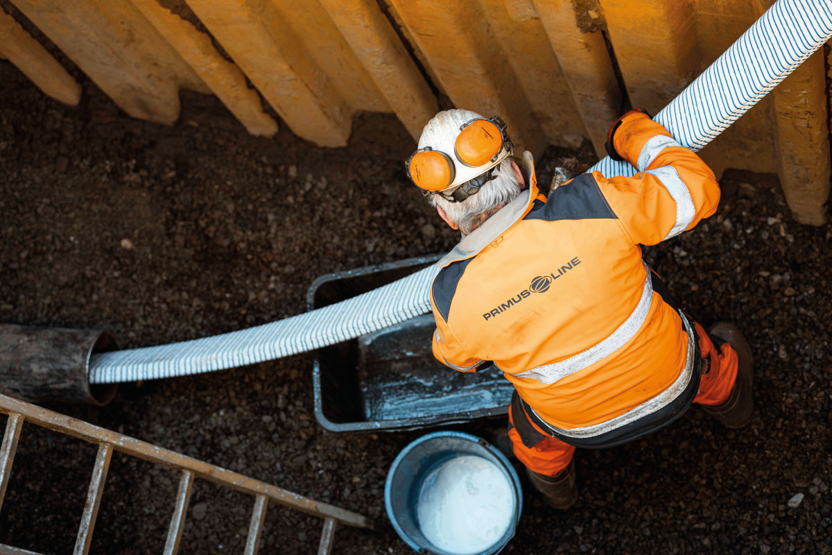
Cement grout (at approximately 25 tons per day) was prepared in a special, large-capacity mixer and conveyed, using a pneumatic drive, through hoses to the distribution head on the cement spraying machine. The spray machine was pulled through the pipeline using special winches.
To assure an even thickness of the lining cement, a constant speed of advance for the machine was set in accordance with the mixer performance and pipeline diameter. The minimum lining thickness was to be 10 mm, with a tolerance of +3 mm. The cement spraying operations in the sections S1 to S8 and the entry shaft was highly exacting in terms of both time and technology. This was due to the longitudinal profile of the pipeline.
For example, between sections S7 and S8, the pre-work inspection uncovered a vertical section open to a height of some 4.5 and 192 m long that was not recorded in any available documentation. Ultimately, this section had to be hand-cleaned and the section cemented manually. Further to this, in section S7, a different pipeline configuration from that shown on the documentation was found.
In these sections the pipeline passed under local roads three times and in one place under a brook.
After careful evaluation of the progress of Phase 1, the work crew was enlarged and divided into a cleaning group and a cement spraying group. This measure achieved better results and in sections S9 to S28 the daily performance rose to 250 to 300 m of completely cleaned and cemented pipeline. The longest section cemented in one plant operation was 514 m.
In this second phase, the greatest workload was during the cement spraying of Sections S9, S10 and S11, totaling 836 m in length. This was due to the unavoidable location of the installation shaft for section S10, which had to be located close to a water course, an overhead power line mast and a local road. Another complication was that the groundwater level was at about 1.4 m above the pipeline crown, which meant that under normal circumstance there was more than 3 m of water in the shaft.
These sections were initially bypassed and the rehabilitation works here were undertaken at the end of the project. Water in the shaft for section S10 had to be pumped out using three high-capacity pumps running for nine days, and special shuttering had to be used to maintain access.
Manual cement spraying was applied to all ‘scalps,’ curvatures, Ts, technological connections and the sections immediately preceding and following the shafts. Manual cement spraying also had to be used in those areas of the pipeline that deviated from the documentation (such as the vertical section mentioned above, in sections S7–S8).
The completion of the cement spray lining of the individual pipeline sections and the performance of prescribed controls and tests was followed by re-welding the ‘scalps’ in place, including their X-ray control and insulation, the reinstallation of fittings in section S1, the installation of a flow meter in section S3 and the geodetic survey of the pipeline in the installation shafts.
Subsequently, the pipeline was rinsed through three times in succession, disinfected, subjected to pressure tests and water sampling for chemical and microbiological analyses. Finally the feeder was put back into operation.
Conclusion
Trenchless rehabilitation of the DN 1600-mm drinking water supply pipeline was performed to the required quality, free of defects and problems and on schedule. With its scope and parameters, location in the landscape and alignment, the DN 1,600-mm, 22,430-m long drinking water supply pipeline represented an unprecedented application of trenchless rehabilitation of potable water supply pipeline that has to date no equal in the Czech Republic.
Ian Clarke is a freelance writer and owner of No-Dig Media Services, based in the United Kingdom. For more information about the project, visit www.brochier.cz.


