Drill Master: Back to the Basics — Pitch & Roll
An HDD machine is a complex combination of mechanical and electronic systems and every directional drilling installation depends on all systems functioning smoothly. Because a directional unit’s downhole maneuverability is one of its most important features, the guidance system is essential for every directional unit, no matter what its make or model.
To drill straight ahead, the drill string and drill head are rotated as forward thrust is applied. To make a direction change, rotation of the drill string and drill head is stopped and the slant face or orientation of a bent sub housing is positioned so that it is opposite the direction of the desired change in the bore path. On traditional slant face technology, when thrust is applied without rotation, the drill head will move in the direction away from the slant of the face. On systems with a bent sub, when thrust is applied without outer pipe rotation, the housing will move in the direction the housing is pitched or bent. This type of bent sub system is normally used with two-pipe or mud motor drilling systems. The drill head may need to be rotated dependent on soil or rock conditions.
To be able to steer the path of a bore, the machine’s operator must know the position of the drill head’s slant face or orientation of the bent sub housing and be able to monitor its orientation as the drill head or housing is slowly rotated to the correct position for a direction change. Electronic tracking and guidance equipment tells the operator the drill head’s orientation, along with other critical information.
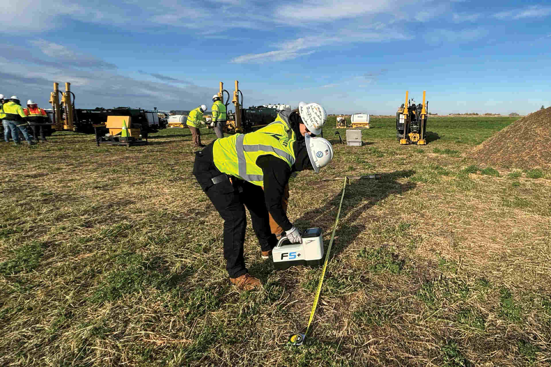
There are at least two methods of basic guidance systems: walkover and non-walkover wireline systems. This Drillmaster Report covers the basic walkover system. Basic walkover guidance systems are comprised of a transmitter mounted in a protective housing in the drill head, and a handheld tracker or locator (we will refer to as receiver) operated by a crewmember who walks directly above the drill head as a bore progresses. The transmitter sends radio signals to the receiver, which processes them and displays the information on a window at the top of the receiver. Data either are relayed to the drill operator by two-way radio or are displayed on a remote display (also a receiver) at the drilling unit’s operator station.
Most electronic guidance systems provide the following information:
- Roll — the position of the drill head’s slant face or orientation of the bent sub housing
- Pitch — angle of inclination of the drill head
- Drill head location
- Drill head depth
- Drill head direction
- Transmitter status, including temperature and battery level
This Drillmaster Report covers roll and pitch.
Roll
To monitor roll, all brands of guidance equipment use a clock face, which appears on displays of hand-held and remote receivers. Most models divide the clock face into 12 segments, although some divide it into 24 segments.
The position of the slant face is indicated on the clock face. To change the bore path, the operator slowly rotates the drill string until the “hand” on the clock is in the position that will result in the desired direction change.
- 12 o’clock takes the drilling head up.
- 6 o’clock is down.
- 3 o’clock is right.
- 9 o’clock is left.
Of course, the face can be positioned at any point on the clock face — 2 o’clock takes the head up and to the right, 8 o’clock is down and to the left, and so on.
It is easy to recognize how useful a remote display can be when making precise direction changes. Being able to see the display reduces the opportunity for mistakes that can occur during radio communication between the crewmember with the receiver and drilling unit operator.
Pitch
Pitch is displayed using an up or down arrow and displaying the percentage of deviation. Pitch is calculated as rise or fall divided by length. For example, a 1 percent change in pitch over a distance of 100 ft is the rise or fall of 1 ft. The reason pitch is used is because it is simpler to figure rise and fall divided by length than to figure angle using trigonometric calculations.
Pitch tells the operator the downward angle necessary to take the drill head to the depth where the path of the bore will be leveled off, and pitch information is used when the drill head needs to be aimed upward toward the targeted exit point or when needing to avoid obstacles.
Pitch also helps the operator keep drill pipe bend radius within acceptable tolerances. Bending the pipe more than the allowable maximum pipe bend radius will damage pipe or result in breaks at joint connections.
The allowable minimum bend radius will vary with the size and model of machine and brand and size of pipe, so it is essential to know manufacturers’ specifications before beginning any installation.
Pay attention to the manufacturer’s recommendation on maximum drill pipe bend radius as a rule of thumb on the percentage pitch change in any 10-ft length of pipe. The pipe bend radius is dependent on pipe size and material. Sometimes it is the bend radius of the product being installed that is the limiting factor; refer to the manufacturer’s recommendation. Depending on the electronic equipment being used, the computer will calculate the bend, or it is easily figured by referring to the pitch at the start of a direction change and keeping corrections within the percent target limit.