2005 New Installation Winner
March 12, 2005
 The City of Portland, Ore., is in the midst of a huge infrastructure projectthat involves controlling 55 combined sewer outfalls to the nearby water bodiesin the city service district. In August 1991, the City of Portland Bureau ofEnvironmental Services entered into an agreement with the Oregon Department ofEnvironmental Quality to control 55 combined sewer outfalls to the nearby waterbodies in the City of Portland service district by December 2011.
The West Side Combined Sewer Overflow program (WSCSO) is the third of fourphases of the combined sewer overflow program. The pipeline project is one ofthree major elements of the WSCSO project, which includes the construction of adeep tunnel (14 ft in diameter) and a 220-mgd pump station. The WSCSCO pipelineproject is scheduled for completion by Dec. 1, 2006. A portion of this massiveproject involved three incredibly challenging microtunneling sections to beinstalled in order to construct new pipelines to control 16 combined seweroutfalls located along the west bank of the Williamette River in the City ofPortland.
The WSCSO Pipelines project is primarily a new construction project thatconnects to the existing sewer systems at various locations to augment theoverflows from the old system to this new pipeline. The design phase for thepipeline project started in March 2001, with construction beginning in September2002.
The pipeline project consists of three primary elements: Southwest ParallelInterceptor Project (SWPI), which is 7,400 ft of 72- and 84-in. pipe; the TannerProject, which involves 1,400 ft of 72-in. pipe; and the Peninsular Force mainProject (PENFM), which involved 1,300 ft of 108-in. steel casing pipe.
The SWPI Project is in the City’s southwest commercial district, which isundergoing redevelopment that will allow high-rise buildings to house commercialand residential properties. The primary businesses in the area include a hotel,commercial and industrial facilities. The alignment passes under the City’smajor utilities, two bridges, railroad tracks and a major traffic feeder toPortland’s City Center.
The Tanner Project is located in the City’s northwest industrial andcommercial district. This area is also undergoing redevelopment that includescommercial and residential facilities. The alignment passes under one interstatebridge, railroad tracks and a major traffic feeder to Portland’s CityCenter.
The PENFM is located in the City’s Swan Island industrial area, passingprimarily under the Union Pacific Railroad (UPRR) main rail yard.
Why Microtunneling
Microtunnelingtechnology was selected for the installation of these pipelines mainly due tothe depth (20 to 80 ft), the high ground water table, the presence ofcontaminated soil and to eliminate the need to replace and relocate numerousutilities, such as its large water supply and distribution mains, high-pressuregas lines, fiber-optic utilities and existing facilities.
The PENFM pipeline crosses under the UPRR main rail switchyard (which has 20main tracks). Installing the pipeline via open-cut in the UPRR would require theshut down of a majority of the rails at a time and would have greatly impactedthe UPRR’s rail operation.
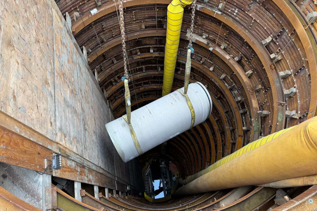
The primary elements of the microtunnel work included the relocation ofexisting utilities in the vicinity of the jacking and receiving shafts,construction of the jacking and receiving shafts and the installation of thepipeline between each shaft. The jacking and receiving shafts were generally 22ft in diameter and constructed of secant piles with a jet-grouted bottom andjet-grouted zones for the entry and egress of the microtunneling machine, aHerrenknecht Mixshield MTBM AVN 1800D.
The jacking distance between shafts varied from 90 to 1,500 ft separation.The microtunneling rate averaged about 150-ft per day. The first shaft wasconstructed in May 2003 and was completed in June 2004; this involved 11 shaftsvarying in depth from 20 to 70 ft. The first phase of the microtunnelingactivity was for the installation of the 84-in. diameter concrete pipe (3,250ft), then the machine was re-sized to install the 72-in. diameter concrete pipe(5,550 ft), with the final re-size of the machine to install the 108-in.diameter steel casing pipe (1,300 ft).
Challenges
There were numerouschallenges encountered during the microtunneling. The alignment is designed tointersect with existing outfall pipes adjacent to the Willamette River. Ingeneral, these areas have been built up over the years due to the variouscommercial and industrial uses. Much of the area has been filled to extend theriverbank, resulting in unknown fill that may contain old concrete debris, brickor other manmade obstructions. It was important to properly balance the facepressure in front of the cutterhead at the transition from the fine silts, loosegravel and cobbles found in the native material to mitigate ground settlement.The Herrenknecht MTBM was able to handle the varying soil conditions, especiallyin the areas of settlement control and obstruction removal.
Crews did encounter obstructions — steel piles, large boulders, largequantities of wood debris — during the microtunneling drives. The HerrenknechtMTBM was equipped with an airlock for obstruction removal. The airlock provideddirect access to the cutterhead under compressed air and eliminated the need toinstall emergency rescue shafts. This feature proved invaluable when the MTBMstruck an unanticipated 10-in. diameter steel pile supporting a shallowelectrical duct bank. The obstruction at this location was 65 ft deep and 50 ftbelow the groundwater table. The sinking of an emergency rescue shaft at thislocation was estimated to be approximately $1.5 million and would have resultedin a delay in the project by several months. In lieu of sinking the shaft, aseries of hyperbaric interventions were used to cut the pile into sections andremove them through the face of the machine. The downtime for removal of theobstruction, repair of the cutterhead and resumption of microtunneling was onlynine days. The entire recovery effort resulted in a direct construction cost ofapproximately $100,000 — well below the estimate for an emergency shaft.
Wood debris was also encountered continuously in about a 100-ft section ofthe SWPI microtunneling drive. Because the cutterhead was designed to handle theanticipated wood debris, the machine was able to progress through it. The MTBMadvance rate was reduced and the slurry inflow adjusted to stabilize the face bybalancing the incoming and outgoing slurry flows to generate a positive pressurein the working chamber behind the cutterhead, resulting in minimal groundsettlement and an additional five days to complete the microtunneling drive.
Installation of the 72-, 84- and 108-in. pipelines was completed using asingle variable diameter microtunneling machine. The expansion kit included ashield skin for each MTBM section, a cutterhead and a push ring to adapt theMTBM tail to the pipe spigot configuration. The drive lengths for themicrotunnels ranged from 90 to 1,500 ft. Increasing the drive lengths allowedthe elimination of two shafts and resulted in significant cost-savings for theproject.
The total cost of the microtunneling on the project was approximately $32million. The microtunneling aspect of the project was completed in July 2005.Work continues with the construction of the manhole structures inside theshafts.