Troubleshooting in the Field
 You are on location in the middle of a bore and everything seems to be running fine. Then WHAM — you’re down. The inevitable “gloom of doom” overcomes you as your mind is telling you “time is money.” Have a diagnostic checklist readily available and train your field personnel on how to perform a methodical and thorough system review immediately in the field.
The following article focuses on several important items to remember when you are under the gun and are often overlooked by even the most trained eye.
Equipment Set-up and Start-up
Be certain that your equipment is level at start-up, it remains level and all the bearing/rotating parts are greased regularly.
Linear Shakers
Linear shakers (common on most of the newer recycler systems) are efficient solids removal tools when they are properly set up. Screen selection can be the most critical item in need of attention when setting up to drill on a new location. Particle size of the cuttings returning from the borehole can change from one job to the next and require prior planning before arriving on location. If you do not have an adequate selection of screen sizes, you will be at a disadvantage before you begin drilling. Here’s an important tip: Purchase and carry a sand content kit on every job location. If you run into material that is foreign to you, this kit will give you the ability to perform a very simple test to provide you and your screen provider with the amount of particles that will not pass through a 200-mesh screen (i.e. sand size particles). Proper screen selection can be determined over the phone and on their way to your location.
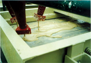
Solids on a properly operating linear shaker will set up in rows and march off the end of the shaker like military soldiers on a parade field. If not, you potentially have a problem with your shaker(s) or one of the shaker components. Ensure the screens are installed correctly and tight against the shaker frame. If screens are properly installed, then check the vibrator motors that operate the shaker(s). There are two vibrator motors on each linear shaker; these motors normally have two counterweights, one on each end. The counterweights on both motors (when observed from the same end) should be turning opposite to each other. It does not matter the direction of rotation as long as it is opposite of the other motor.
A common problem when drilling is discharging too much liquid off the end of the shaker. It not only creates a huge mess to cleanup but unnecessary headaches with drilling location management. The size of the particles returning from the borehole has a lot to do with screen selection for each job. These particles can change from one job to the next and from one formation to the next. As a general rule of thumb, the fluid should “pool” about one-third of the shaker screen area and dry up into solids “marching” for the remainder of the screen bed. This is a starting point and not always achievable.
Solids returning from the borehole can be the same size as the openings in the screen and can wedge themselves into the openings of the screen. The blockage of the screen opening creates a solid surface that will not allow the fluid to separate and return into the system for reuse. When this occurs, it is almost impossible to see the blockage without removing the screens, washing them off and holding them up to the sunlight or light source.
At this point, from the bottom of the screen, you will be able to see the blockage in the screens. This can be resolved a couple of ways. If the problem is on the scalping side, the screen size can be increased or decreased. Larger screens will allow the solids to pass through and this will increase the workload of the cones as they have to work harder to remove the additional solids. An alternative corrective method is to place smaller mesh screens on the scalper shaker. In theory, the smaller openings will allow the solids to pass over the screen and allow the fluid to re-enter the system.
When you have a blockage on the cone side, it is always recommended that you go to smaller screens (if at all possible) to prevent the solids from re-entering the system. Drill fluid that is not too thick will always increase the ability of the recycler system to perform optimally thus saving you money. If it is necessary to run the drilling fluid as thick as “oatmeal” or “ice cream,” add fresh water at the scalping shaker to allow the solids to “breakout” of the fluid for removal.
Cone Manifolds (Hydro Cyclones)
When operating properly, the cones create a vacuum at the discharge of the Apex rubber on the cone (this is the solids discharge point of the cone). The cones vacuum can be checked by carefully placing your finger over the discharge opening and if you feel suction (like the suction on a vacuum cleaner hose), the cone is flowing free and sweeping solids. It should be noted that the normal operating pressure on a hydro cyclone should be in the 20 to 45 psi range. Certain styles of cones will operate at a lower pressure than 20 psi but it is my personal belief that the efficiency at this low a psi is greatly reduced.
Cone pressure can be checked at the gauge near the cone manifold inlet. A common problem we hear from the field is that the cones are dumping a large amount of liquid out the bottom of the cone (apex opening). Each cone consists of three openings: the pressure inlet, the pressure outlet and the solids discharge. If the discharge opening is plugged (usually by a rock, stick or foreign object not processed over the shaker), it will have no choice but to dump the pressure liquid out the bottom. This scenario can also occur in reverse where the inlet is blocked and discharge pressure from other cones on the manifold flows into the outlet of the blocked cone and out the solids discharge port. Foreign objects can be from “trash” in tanks left over from the last job, materials out of nearby trees, tools or rocks accidentally knocked off the boots of workers on top of the unit. It is important to check for any debris to ensure that the cones are not and do not become obstructed.
Remember, the cones are designed to sweep solids out of the drilling fluid within a certain pressure rating. When the pressure of the inlet flow falls below 20 psi, in most cases the cones start dumping the inlet flow out the bottom of the cones. This occurs due to insufficient pressure to maintain the cyclone action and push the fluid out the discharge port. The causes may be one of the following: (1) the suction is blocked off with dried drilling fluid or solid foreign material in the suction line; (2) the impeller in the centrifugal pump is worn to a point where it cannot provide the proper amount of flow and pressure; (3) the centrifugal is turning backwards (opposite rotation from design); (4) bad power source: (electric, hydraulic or mechanical); (5) a torn or broken centrifugal coupling; or (6) an empty tank or low tank volume.
The amount of solids entering the cone manifold can become extremely heavy, especially during a pullback operation. This can lead to an overload of the cone manifold in some or all the cones. The cones can block off in the funnel section, preventing the solids from properly discharging and allowing solids to re-enter the system. If the vacuum is not present at the Apex of the cone, use a welding rod or something similar in length and diameter to correct the obstruction. Simply bend one end of the rod about 1 to 2 in. at a right angle to prevent the system from pulling the rod into the manifold. Then, work the rod up the bottom of the cone in a circular motion to free any jammed solids and allow them to fall out of the Apex thereby freeing the discharge of solids. Very important: Be sure that you have bent the rod you are using or the system will pull the rod up into the manifold.
When a cone is operating properly and there is a low amount of solids in the drilling fluid, the cone will have a tendency to throw more liquid onto the screen. To lessen the amount of liquid, adjust the Apex nut tighter, which reduces the diameter of the hole. When the drilling fluid is heavily laden with solids, opening the Apex nut and increasing the diameter of the hole will increase the amount of solids discharge from the cone.
Properly operating cones should have a vacuum suction at the Apex opening, an inlet pressure of the cone manifold between 20 and 45 psi, and the solids discharge pattern from the cone of either a fan spray (during normal cleaning) or a roping action of solids (during heavy solids discharge).
Training your field personnel to take the time to properly set-up, run, care for and troubleshoot equipment challenges will save you not only time and money but will ensure the long life of your drilling/recycling equipment.
This article provides a basic beginning framework for you to begin to build your own complete field troubleshooting checklist. Be sure to consult with your equipment manufacturer for any dos and don’ts specific to your particular equipment and warranty.
John I. Miller is CEO of Mud Technology International Inc., which is based in Athens, Texas.