Mechanical Trenchless Point Repair Sleeve with a Locking Gear Mechanism for Pipes of Varying Inner Diameter and Offset Joints
February 23, 2015
Mechanical trenchless repair sleeves with a locking gear mechanism for pipes of varying inner diameter and offset joints in the range of 6 to 72 in. (150 to 1,800 mm) offer many advantages over relining the entire pipe or using other point repair technologies.These sleeves can be used for storm, potable water, wastewater and industrial pipes, conduits and drainage culverts. When the specified materials are used in manufacturing the sleeve and installed in accordance with the ASTM standard F3110-14, the renovation extends over a predetermined length of the host pipe as a continuous, tight-fitting, leak-free and corrosion-resistant repair.
Given that each owner retains the right to choose the test protocol to verify the efficacy of these sleeves for its ability to provide a leak free repair, the producers have not provided any test protocol of their own. The maximum internal pressure this sleeve can carry depends on the diameter and the wall thickness, ranging from 147 to 214 psi (1.0 to 1.5 MPa); the external pressure cannot exceed 21.4 psi (0.15 MPa). All materials in contact with potable water are certified to meet NSF/ANSI 61/372.
More than 200,000 sleeves have been installed globally for repairing the following types of defects in pipe: longitudinal, radial and circumferential cracks, fragmentation, leaking joints, displacement or joint misalignment, closing or sealing unused laterals, corrosion, spalling, wear, leaks in the barrel of the pipe, deformation in the pipe and root penetration. There are no limitations on the diameters of the laterals that can be sealed.
The degree of deformation that can be repaired is dependent on the minimum and maximum diameters for which the sleeve is applicable. Repairs can be made of vitrified clay, concrete, reinforced concrete, plastics, glass reinforced plastics, cast iron, ductile iron and steel. The suitability of the technology for a particular application shall be jointly decided by the owner, the engineer and the installer.
 Components Forming the Sleeve

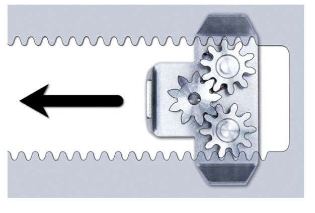
A stainless steel sleeve with flared ends faces the direction of flow and improves the hydrodynamics, prevents solids from depositing, and increases jetting resistance shown as (1) in Figures 1 and 3. Flared ends are not used, however, for potable water applications; metal overlap is for expanding to the pipe wall shown as (2) in Figure 1. The locks that keep the sleeve expanded run along the toothed strip shown as (3) in Figure 1; the lock is a small set of gears that only moves in one direction, thus keeping the sleeve expanded shown as (4) in Figures 1 and 3.
The locking gears are also shown in Figure 4. There are three gears per lock. Six gears per sleeve. Two of the gears in the lock ride in the corresponding “teeth” in the sleeve. The third gear is the lock. It allows the other two gears to only move in a forward direction. The gears and the shield are all of the same material as the rest of the sleeve. Furthermore, the gears are protected by a cover to prevent snagging of waste, or buildup of sludge or sediment.
Adhesive tape and plastic screws are put on at the factory to protect the sleeve during transport and prevent it from unrolling shown as (5 and 6) in Figure 1. Circumferential seals are formed by the rubber compressed against the host pipe. The damaged section must always be between the sealing knobs shown in (7) in Figures 2 and 3. There is a trimming line marked in the rubber jacket. It shows the installer where to cut off the projecting rubber end shown as (8) in Figure 2. The projecting rubber end acts as a seal between sleeves installed in series shown as (9) in Figures 2 and 3.
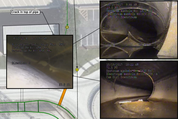
Inspection and Preparation of Damaged Pipe
Before using the sleeve, the pipe must be inspected to ascertain whether it can be repaired with the system. Cleaning and inspection shall be as per NASSCO guidelines for sewage pipes. For other pipes, cleaning and inspection methods that are acceptable to the authority shall be chosen by the installer. There must be at least one access via a manhole or an inspection chamber. The manhole must have a diameter of at least 24 in. (600 mm) so that the camera/packer system can be inserted. The interior of the pipeline shall be carefully inspected to determine the location of any condition that shall prevent proper installation, such as roots and collapsed or crushed pipe.
The pipe to be repaired must always be cleaned with a high-pressure jet, a drag scraper or an equal approved by the owner, the owner’s representative or the manufacturer, before using the sleeve.
Materials
The sleeve is made of high grade 316 or 316L stainless steel. There are three types of sleeves available: non-flared, one end-flared and both ends flared. Non-flared sleeves are mainly used for potable water applications or serial installations, followed by one end-flared sleeves. The both ends flared type is used for single installations only. EPDM seal or silicon rubber seal (for potable water with chlorine or fluoride treatment or even EPDM washed with peroxide) meets the physical property requirements for elastomeric materials used in cold water supply, drainage, sewerage and rainwater systems for Type WC in Table 2 of EN 681-1 Hardness Category of 40. NBR and similar elastomers may be appropriate for other effluents or where contaminated soils are surrounding the exterior of the pipe.
Installation
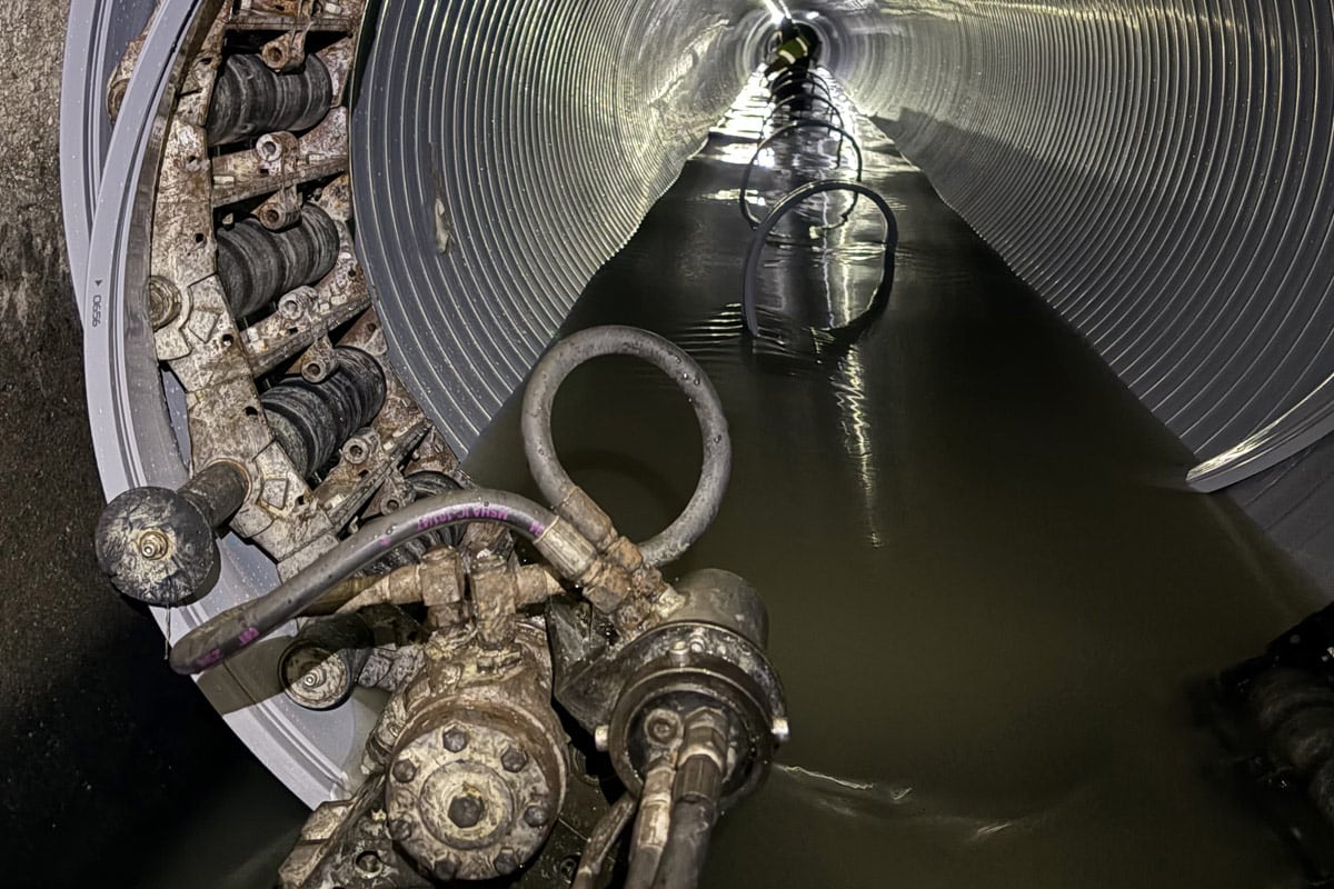
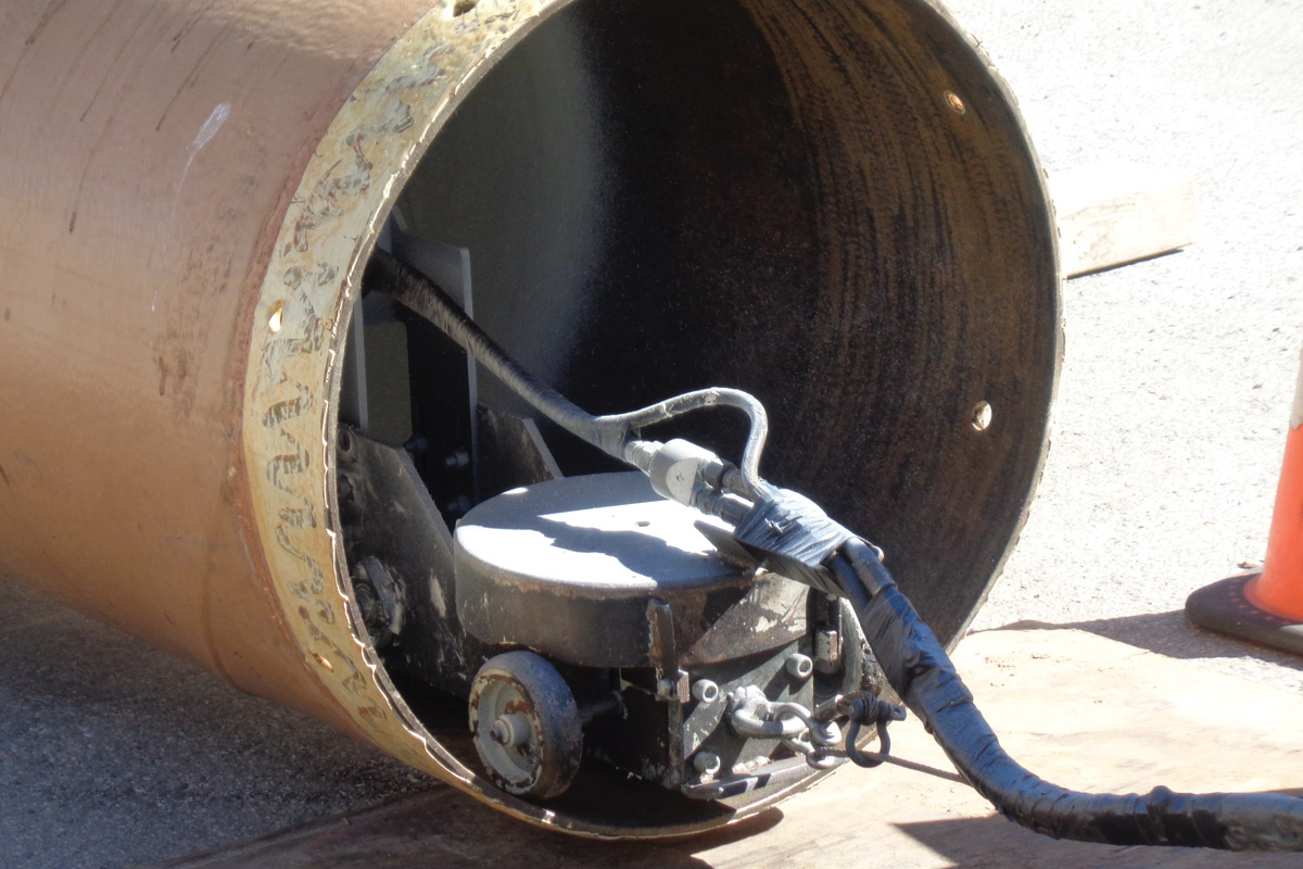
The sleeves in pipes up to 32 in. (800 mm) are installed using a packer. The packer is usually connected to the camera or robot via a bracket and a hollow link bar. For repairs more than 20 ft (6 m) into the line, the sleeve is installed most efficiently and accurately when the packer is positioned by using a crawler camera equipped with an accurate distance counter.
The sleeve is usually positioned on the packer while in the manhole. If the installer is using a packer equipped with a laser, position the sleeve so that the laser beam is reflected both on the edge of the sleeve and the host pipe. Installation in pipe sizes larger than 32 in. (800 mm) is done manually. Depending on the quantity of flow present, bypassing in accordance with the authority’s requirements may be necessary.
The above sleeves are here to stay given the mantra “doing more with less,” and it is only a matter of time that the total number of sleeves used in the United States would become higher than all other countries around the globe in a given year.
Dr. Jey K. Jeyapalan is the owner of Civic Enterprises LLC, which offers training, consulting, market studies, failure investigation and expert testimony in underground infrastructure such as pipelines and penstocks. He is also the author of “Advances in Underground Pipeline Design, Construction and Management.”
Tags: 2015 February Issue